Geotechnical engineering projects contend with complex geological environments and the risk of engineering-related hazards. Excavation activities—such as those for tunnels and roadways—can trigger instability and sliding along nearby faults or structural planes. These movements frequently exhibit "stick-slip" characteristics, a phenomenon linked to the non-uniform stress distribution across the fault plane caused by excavation and the complex internal structure of the fault plane itself.
Scaled physical modeling is an experimental technique offering controllable parameters and intuitive results; it enables the simulation of the overall deformation of rock and soil masses during excavation and faithfully reproduces the structural relationships associated with their failure, making it widely applicable in the field of underground excavation engineering.
Measuring displacement fields and morphological changes is a primary objective in model tests using similar materials, serving as the foundation for further analysis of the model's mechanical behavior. Traditional observation methods—such as displacement transducers, accelerometers, and differential GPS—rely primarily on contact-based measurement. These methods require sensors to be physically attached to the structure, creating installation challenges in practical applications, while multi-point measurements are time-consuming, labor-intensive, and costly.
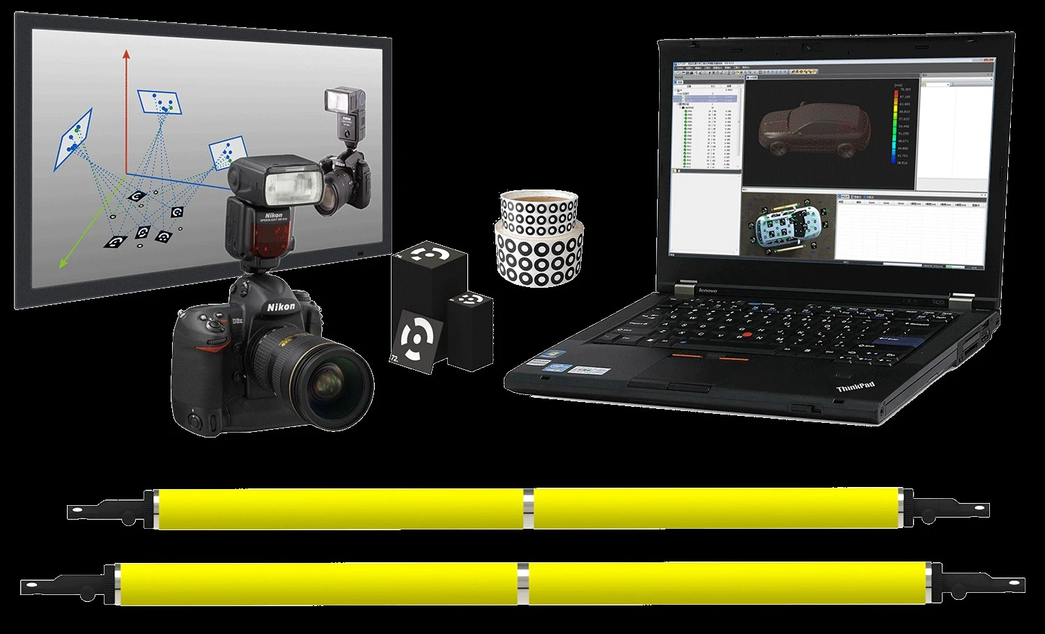
The XTOP3D XTDP 3D optical photogrammetry system utilizes industrial close-range photogrammetry technology. By calibrating internal and external camera parameters and employing pattern recognition for feature point tracking, it enables full-field structural displacement measurement. This computer vision-based, non-contact testing approach overcomes the limitations associated with multi-point displacement monitoring and measurement ranges; it offers simple installation and high sampling rates while eliminating the interference that physical contact can cause to the test object.
In the application of structural displacement measurement, the photogrammetric process involves: capturing images of pre-positioned feature points on the structure using industrial cameras; calculating the 3D coordinates of these feature points through data processing; and determining displacement by comparing the coordinates of the feature points at different time points.
Design of the 3D Photogrammetry Scheme
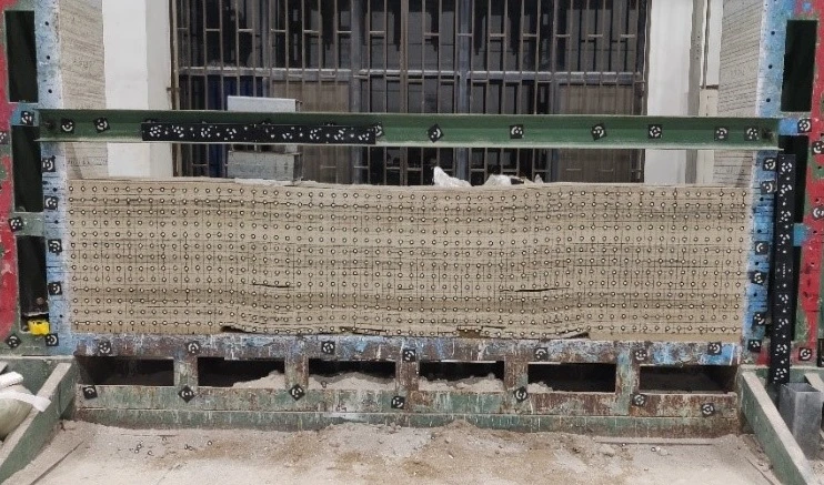
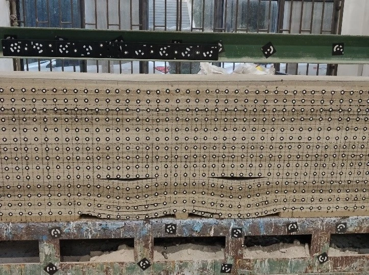
Control points (coded points) are positioned on the sides of the model frame and on the upper and lower crossbeams. Observation points (non-coded points) are distributed along the rock and soil strata; the spacing between rows and between points is determined based on the object being measured and the model scale.
Observational data from the similar-material model, collected at different time points, must be transformed into a unified coordinate system for comparative analysis. Global reference points for coordinate transformation must be identified, and scale bars for scale calculation must be selected and securely fixed in appropriate locations.
Model Data Acquisition
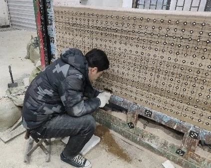
Data acquisition was performed using the XTDP 3D optical photogrammetry system. To ensure multi-angle and multi-level coverage, images were captured from various positions and angles.
Photography of the excavation process in a scaled model
Data Processing
Industrial cameras were used to photograph pre-positioned feature points on the structure. XTDP software was then employed to calculate the coordinates of both coded and non-coded points; displacement was subsequently determined by comparing the coordinates of the feature points at different time intervals.
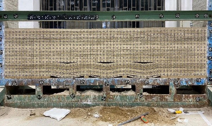
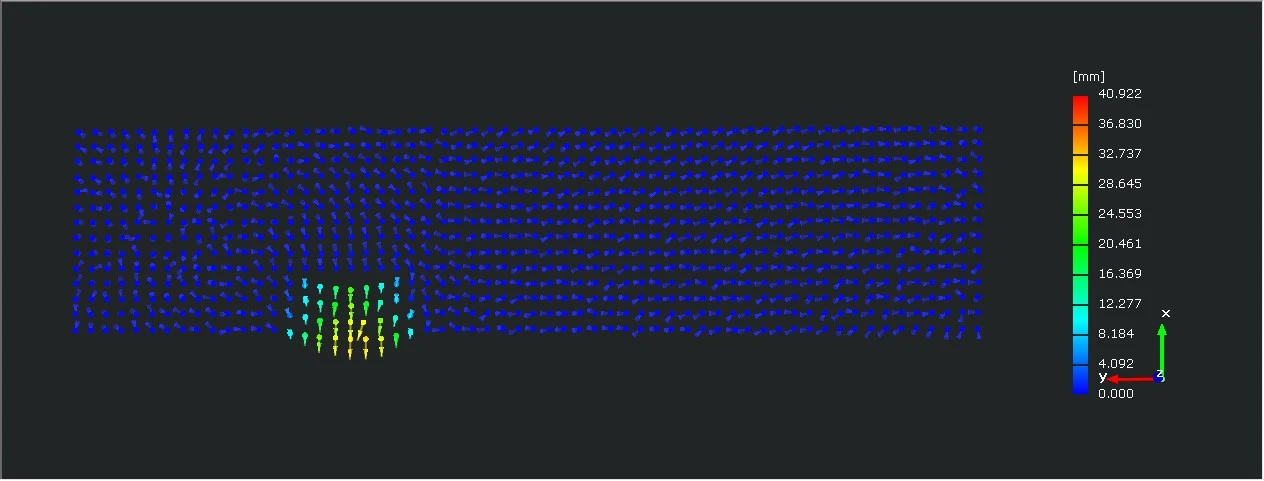
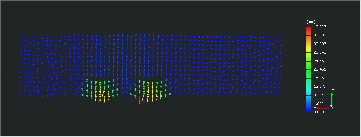
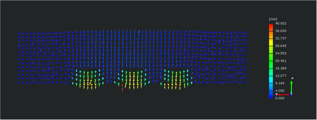
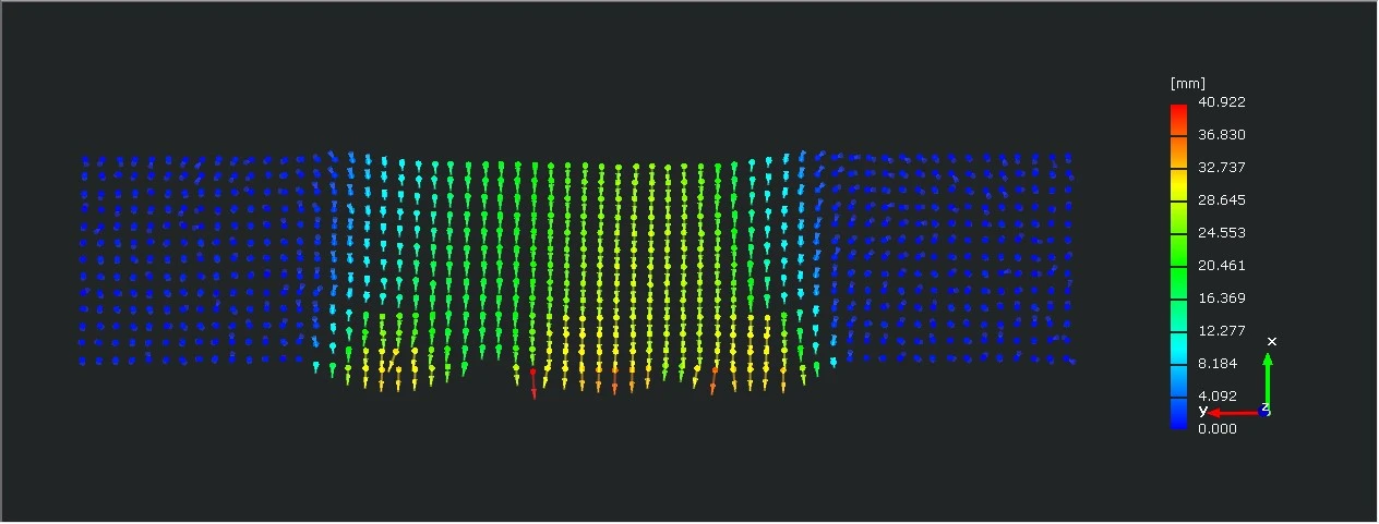
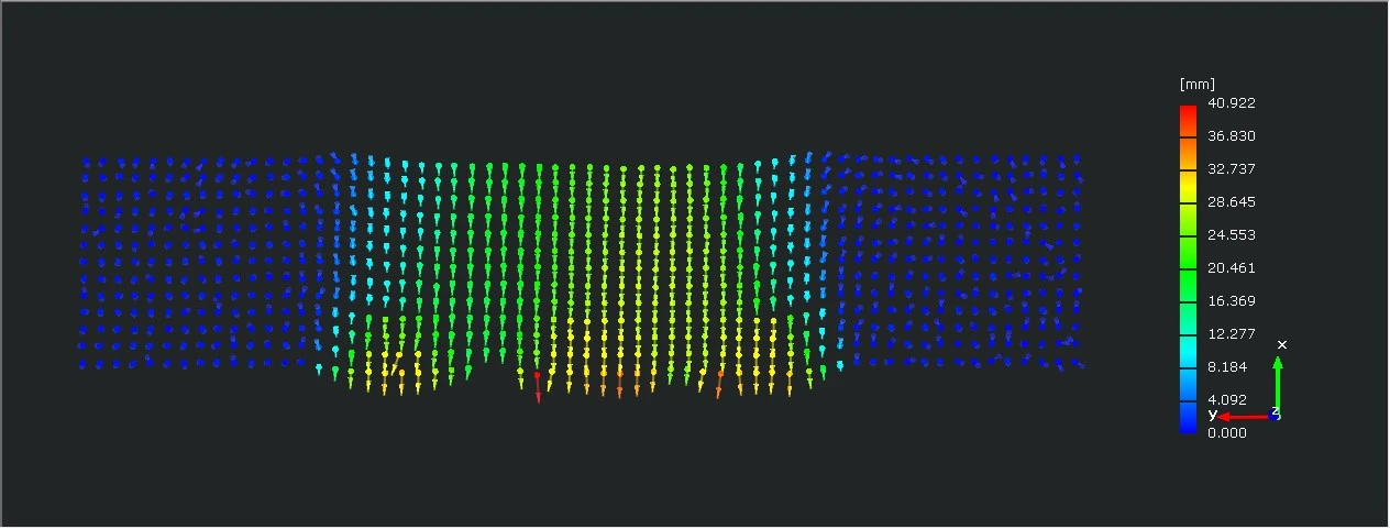
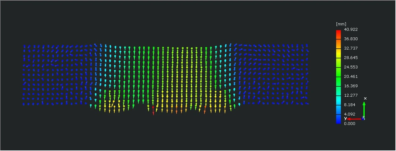
The results demonstrate that applying the XTDP 3D optical photogrammetry system to monitor the similar-material model effectively captures the patterns of excavation-induced settlement.
3D optical photogrammetry is employed to monitor the deformation of physical models made of similar materials; it enables the acquisition of extensive geometric data, making it particularly suitable for models with a large number of observation points.
Images captured by the XTDP 3D optical measurement system can be verified at any time, and the system records the displacement of all points at the moment of photography. This allows for the monitoring of the overall deformation of large-scale physical models while ensuring measurement accuracy, thereby providing an experimental basis for further research into deformation and subsidence patterns associated with geotechnical excavation.