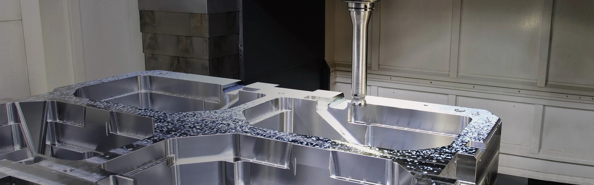
Molds form the foundation of industrial manufacturing; the quality of mold design directly determines the excellence of finished products—whether produced via injection molding, die-casting, or stamping. Systematic errors during the design phase lead to compounding, high-cost modifications during subsequent machining, mold trials, and mass production. Mold design requires the integration of multiple structural elements—such as parting lines, gating systems, cooling channels, draft angles, shrinkage compensation, and ejection mechanisms—where interdependent parameters make design decision-making highly complex.
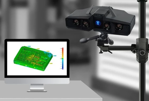
Traditional mold design relies solely on engineer experience and CAE simulation, lacking a means for physical validation prior to machining. The XTOP3D XTOM blue-light 3D scanner supports the entire mold development process by providing a high-precision, full-field 3D digitization solution; this addresses gaps in design validation, ultimately reducing costs and enhancing efficiency.
I. Key Pain Points in Mold Design Verification
1. Lack of upfront physical validation: Reliance solely on simulation—which may deviate from actual operating conditions—means issues often surface only after mold trials, resulting in extremely high modification costs.
2. Absence of comprehensive quantification tools for complex surfaces: For products with free-form surfaces, only cross-sections can be spot-checked, making it impossible to fully evaluate mold surfaces, draft angles, and fit accuracy.
3. Inconsistent design and machining datums: Misalignment between the modeling coordinate system and shop-floor process datums leads to discrepancies that only become apparent during the mold trial stage.
4. Lengthy design iteration and verification cycles: Modifications require a full machining cycle for re-verification, resulting in high iteration costs and low efficiency.
5. Difficulty in reconstructing legacy molds lacking blueprints: While the physical mold exists, the original drawings are lost; this prevents the digitization of process expertise and leaves repair or optimization efforts without data-driven support.
II. Roles and Limitations of Traditional Approaches
While CAD/CAM software enables the precise creation of 3D models, it cannot perform physical verification or comparison; CAE simulation can predict molding behaviors—such as filling, cooling, and warpage—in advance, yet significant discrepancies often exist between simulation results and actual processing conditions.
Coordinate Measuring Machines (CMMs) can accurately capture dimensions at key points, but discrete point data fails to provide a comprehensive assessment of the overall surface design quality; mold trials serve as the final verification step, but discovering defects at this stage entails lengthy rework cycles and substantial economic losses.
Although traditional methods each have their merits, they suffer from systemic shortcomings regarding the core objective of mold design: verifying design quality quickly, comprehensively, and cost-effectively prior to manufacturing. This is precisely where blue-light 3D scanning technology adds critical value to the mold design process.
III. Application Value of Blue-Light 3D Scanning Technology
1. Reverse Digital Modeling
Suitable for scenarios involving legacy molds lacking blueprints, reverse engineering of prototypes, and replication of imported molds. Blue-light 3D scanning captures high-density point cloud data across the entire mold surface; subsequent processing via reverse engineering software enables the creation of editable CAD models that faithfully reproduce surface details, facilitating the digital archiving of legacy molds and the reconstruction of reference data for repairing worn molds.
2. Pre-machining Digital Design Verification
A critical application prior to mold production. By scanning raw blanks or 3D-printed prototype molds and comparing the results against the design CAD data to generate deviation maps, users can verify surface profiles, parting line fit, draft angles, machining allowances, and key feature dimensions. Correcting design flaws at this stage significantly reduces the costs associated with mold rework during trials.
3. Data-Driven Process Optimization
Leverages actual 3D scan data to establish a closed-loop design optimization process. Measured deviations inform the optimization of tolerance allocation, shrinkage compensation factors, demolding structures, and gating systems, thereby minimizing defects such as warpage, short shots, and mold sticking. Simultaneously, comprehensive verification data is archived and linked with material properties, wall thicknesses, and shrinkage parameters to build a database, enabling the digital preservation of process expertise and ensuring the traceability of quality issues.
IV. Typical Application Cases
1. Forward Design Verification for Die-Casting Molds
Project Background
Precision die-casting molds feature complex contour structures, and there is a high requirement for "first-time-right" design success. Given the large scale and high cost of these molds, design errors can lead to significant financial losses due to rework and cause project delays.
Application Value
An XTOM blue-light 3D scanner is used to perform full-surface scanning and verification on both the CAD model (design stage) and the first mold sample, confirming the conformity of the manufactured part to the design CAD. Identifying and rectifying issues during the design phase helps shorten the mold development cycle.
2. Reverse Engineering and Optimization of Complex-Surface Molds
Project Background
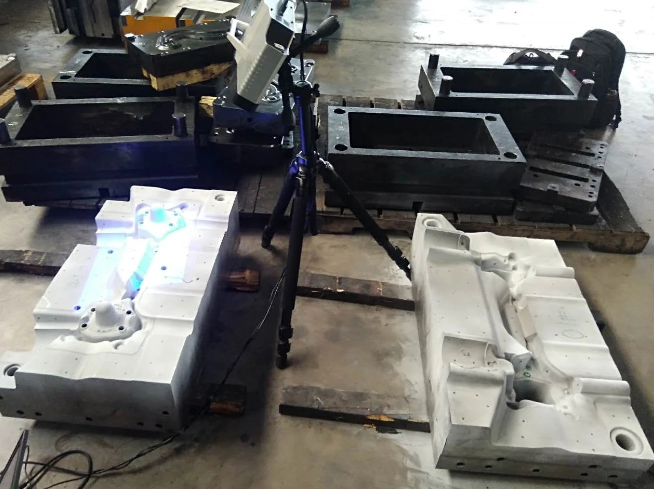
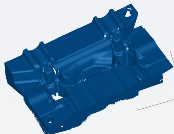
Original mold drawings were lost, while iterative production had resulted in numerous optimized surface profiles; digital reconstruction and an upgrade to a new mold version were required.
Application Value
Blue-light 3D scanning technology enables the reverse engineering of a complete, editable CAD model and the quantitative capture of years of process improvement data. This provides a factual basis for optimizing the new mold, moving beyond the traditional reliance on pure experience for mold modification.
3. Optimization and Verification of Electrode Mold Design
Project Background
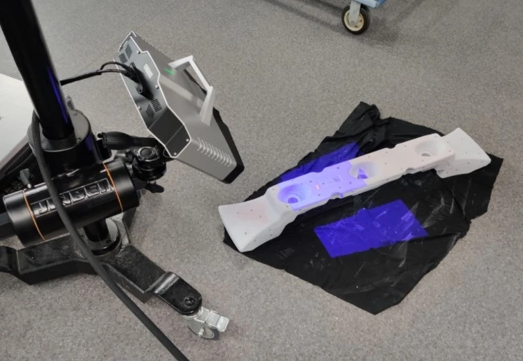
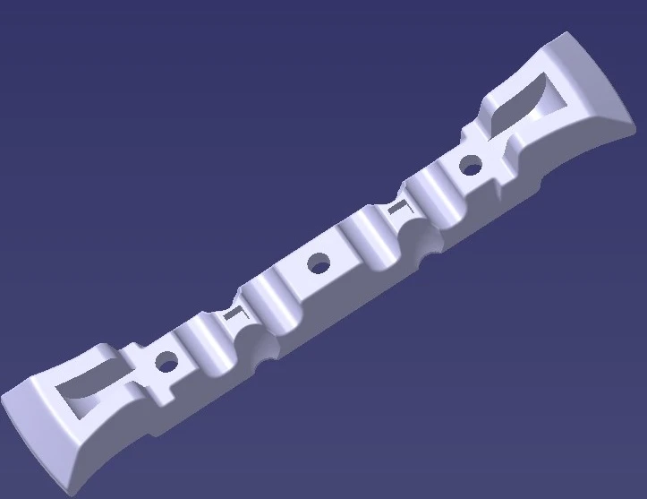
The mold electrodes feature intricate surface profiles and complex textures, demanding high precision in both machining and Electrical Discharge Machining (EDM). Inadequate design allowances or draft angles can necessitate repeated electrode modifications and iterative EDM trials, thereby extending the mold development cycle.
Application Value
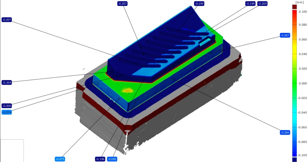
By utilizing blue-light 3D scanning technology, full-field electrode data can be comprehensively captured. Comparing this data against the CAD design generates a deviation color map, allowing for the early correction of design allowance discrepancies and effectively shortening the overall mold machining and verification cycle.
4. Precision Verification of 3C Mold Design
Project Background
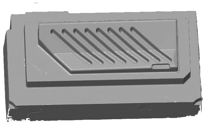
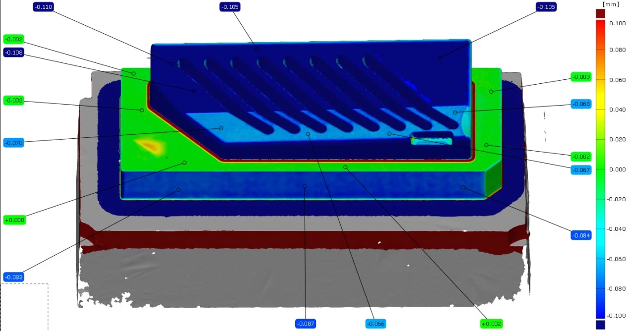
Laptop back panels feature large-area, thin-walled structures with stringent requirements for surface flatness and snap-fit assembly dimensions. Traditional single-point measurement methods cannot fully assess overall surface warpage or deviations in parting-line contact. Post-trial molding issues—such as deformation and excessive assembly gaps—often arise, while repeated mold modifications entail high costs and long lead times.
Value Proposition
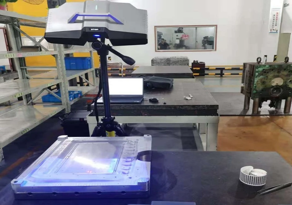
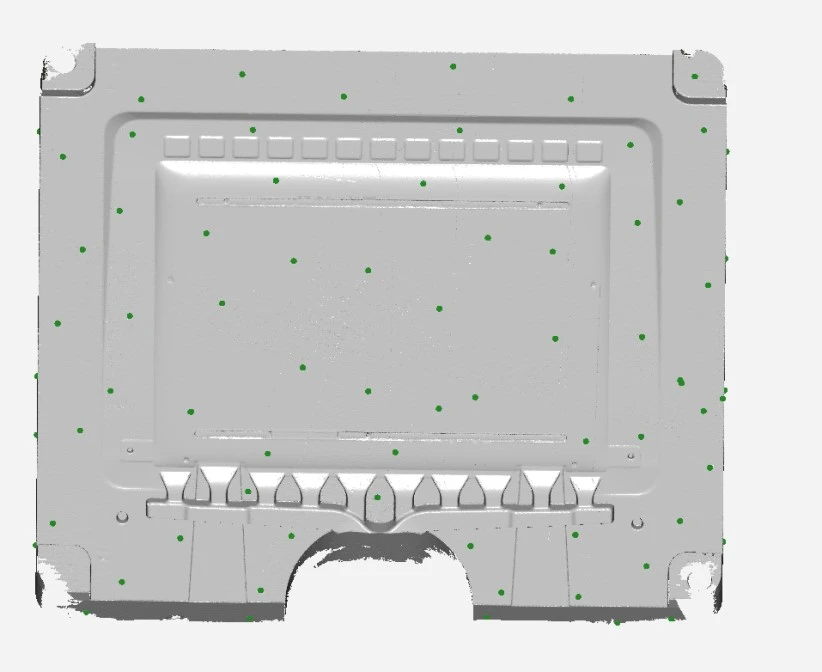
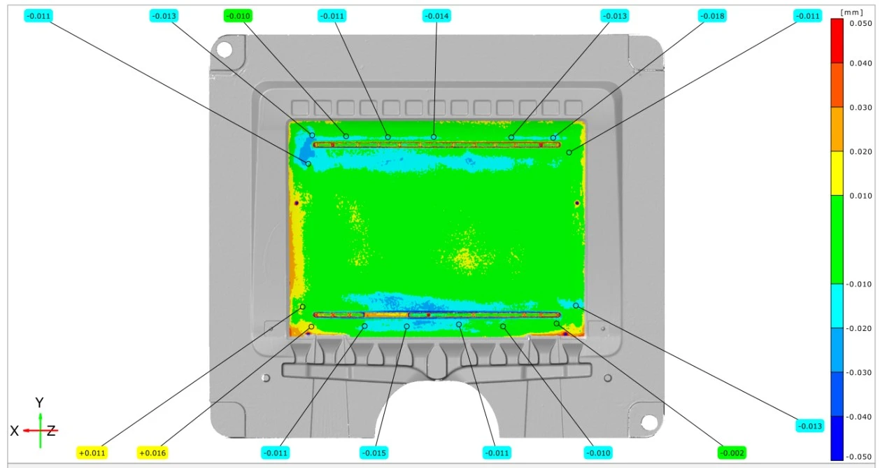
Blue-light 3D scanning technology is employed to perform full-field scans of the mold and the molded back panel, comparing the results against CAD data. This allows for the intuitive visualization of warpage deviation across the entire panel, enabling precise optimization of mold shrinkage compensation and cooling system design. Correcting design flaws early reduces the number of trial molding iterations and shortens the overall project development cycle.
V. Summary and Core Value
Blue-light 3D scanning technology provides a comprehensive, high-precision, and highly efficient digital verification solution for mold design. By deeply integrating into every critical stage of the design process, it offers reliable verification evidence, ensuring that design decisions are well-founded and design iterations are backed by data.
1. Upstream Design Verification:** Shifts verification from the mold trial phase to the design phase, significantly reducing the cost of design errors.
2. Quantitative Assessment of Full Surfaces: Replaces point-based measurement with surface scanning, ensuring design quality is evaluated across every area without overlooking any deviations.
3. Precision Guidance for Mold Modification:Transforms mold modification from "blind adjustments based on experience" to a "data-driven" process, significantly reducing the number of modifications and the overall cycle time.
4. Accelerated Design Iteration:Establishes a closed-loop process—rapid verification, detection, correction, and re-verification—that drastically shortens the design iteration cycle.
5. Digitization of Process Expertise:Converts tacit experience into explicit data, building a design knowledge base that allows for sustainable accumulation of expertise.