Cracks are key indicators of damage and service performance in concrete structures; thus, their accurate identification, dynamic tracking, and quantitative reconstruction are crucial for investigating structural failure mechanisms and assessing residual load-bearing capacity. Traditional monitoring methods—such as dye penetrant testing, strain gauges, and crack opening displacement (COD) gauges—suffer from limitations such as poor micro-crack detection capabilities, contact-induced interference with structural behavior, and an inability to quantify damage parameters, making them inadequate for high-precision monitoring requirements.
This experimental study utilized the XTOP3D XTDIC 3D full-field strain measurement system and non-contact DIC optical testing technology to conduct comparative compression tests on two types of concrete beams: wide-section beams and slender beams. Based on time-series data of full-field displacement and strain, the study compared and analyzed the entire process of crack initiation, propagation, and structural failure for both beam types. The results demonstrate that DIC technology effectively captures early-stage micro-damage in concrete, accurately characterizes crack evolution patterns, and enables high-precision quantitative reconstruction of cracks, thereby providing reliable support for research on concrete structural damage and engineering safety assessments.
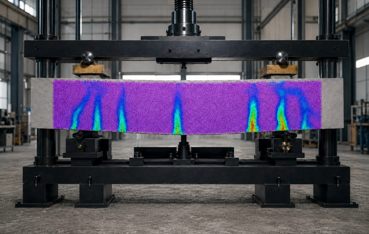
I. Test Program and Testing System
Specimen Design
Two groups of rectangular concrete beams were prepared for this test, with varying cross-sectional dimensions designed to create specimens exhibiting distinct stiffness and structural behavior characteristics:
Specimen 1 is a short, stocky beam with a wide cross-section, characterized by high structural stiffness and significant concentrated load effects;
Specimen 2 is a slender beam with a low width-to-height ratio, exhibiting pronounced combined flexural-shear behavior.
Curing conditions, loading methods, and testing environments were kept consistent across both groups to ensure that the experimental variables were isolated.
DIC Testing System and Test Setup
The test utilized the XTOP3D XTDIC 3D full-field strain measurement system in conjunction with an electro-hydraulic servo testing machine to achieve synchronized loading and data acquisition. Prior to testing, a matte white paint base was applied to the specimen surfaces to create a high-contrast random speckle pattern, thereby ensuring the accuracy of image acquisition and data processing.
During the test, the XTDIC system operated in synchronization with the testing machine to acquire real-time data on load, displacement, and image sequences. DIC algorithms were employed to calculate parameters such as full-field displacement, principal strains, and X-direction strains, enabling a comprehensive record of the mechanical response and crack evolution characteristics from the onset of damage through to structural instability and failure.
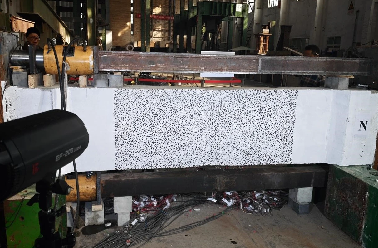
Black-and-white speckled pattern
II. Test Results and Data Analysis
Analysis of Specimen No. 1 (Wide-Section Concrete Beam)
Displacement Field Distribution Characteristics
X-direction displacement: During loading, the maximum X-direction displacement was concentrated at the center of the beam's bottom surface, exhibiting a narrow-band distribution with a steep displacement gradient that attenuated rapidly toward both sides.
Resultant displacement: Exhibited a symmetrical "U"-shaped distribution, with the high-deformation zone confined to a range of ±15 mm directly beneath the loading point.
Mechanical implications: These results indicate that the wide-section beam possesses high stiffness and concentrated load transfer; structural failure is dominated by localized severe deformation, while overall cooperative deformation capacity is relatively weak.
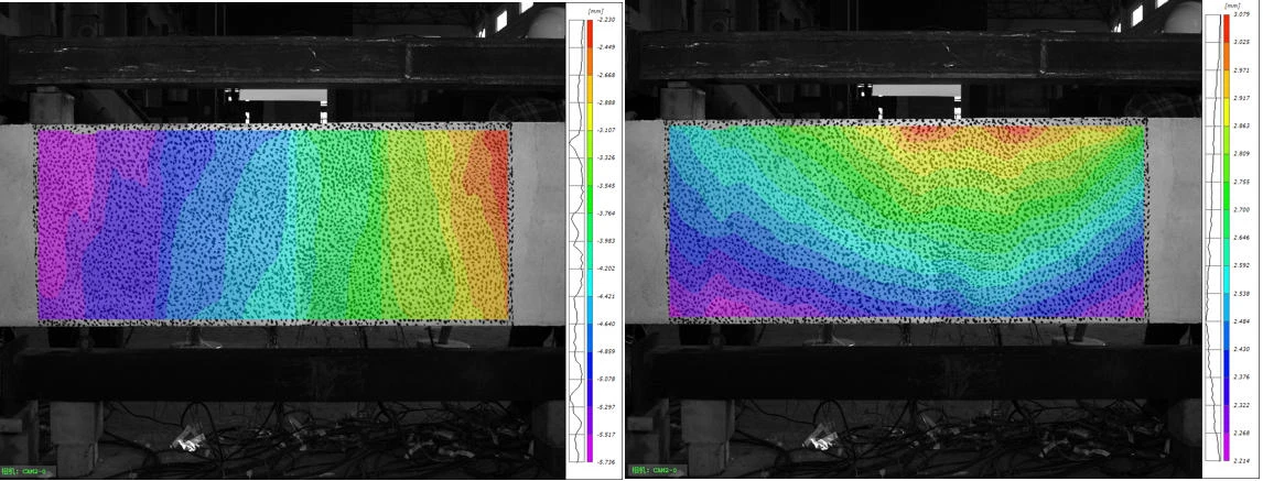
Specimen No. 1 X-displacement & resultant displacement
Strain-Load Response Characteristics
The strain-load response of Specimen 1 exhibits distinct two-stage characteristics: during the initial loading phase, strain increases linearly with the load, indicating that the member is in an elastic state; once the load reaches a critical value, the strain undergoes a sudden jump without a discernible plastic yielding phase. This demonstrates that the wide-section beam undergoes typical brittle failure, characterized by sudden collapse and an absence of significant pre-failure deformation.
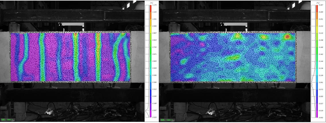
Specimen No. 1: Principal Strain & X-Strain
Select corresponding points on the two specimens and export the data for those points; the DIC software then generates displacement and strain curves for those locations.
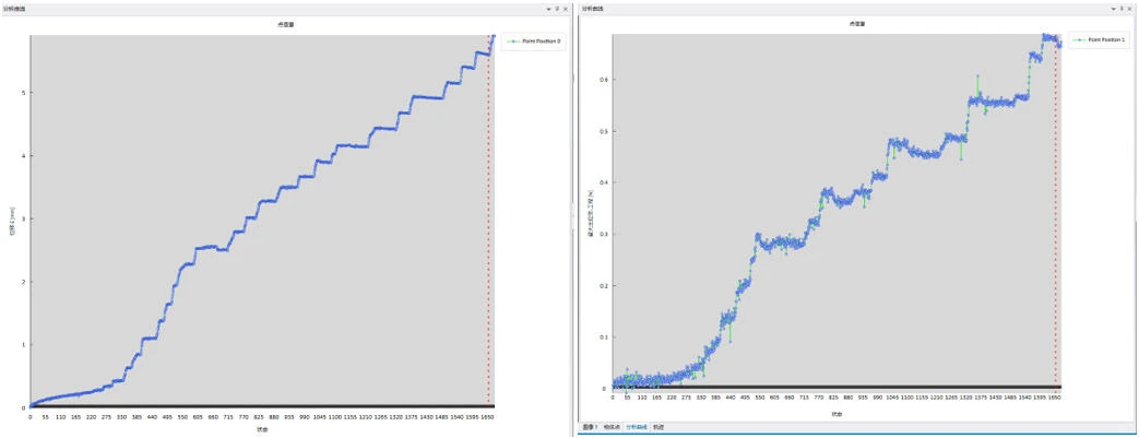
Displacement-Strain Curve for Specimen No. 1
Crack Initiation and Propagation Mechanisms
For Specimen 1, cracks initiated in the region of peak principal strain at the bottom of the beam; the propagation process involved no branching or secondary cracking, following a single, regular path. Under sustained loading, the main crack gradually propagated through the section, ultimately leading to structural failure. The regions of abrupt change in the DIC strain maps corresponded closely with the actual crack locations and propagation paths, enabling precise identification of the core damage zones.
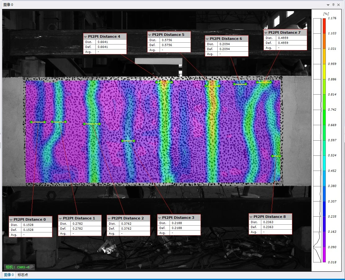
Analysis of Slender Concrete Beam Specimen No. 2
Characteristics of Displacement Field Distribution
X-direction displacement: The maximum displacement for slender beam No. 2 is also located at the center of the beam's bottom surface; the displacement spreads gently in a symmetrical, elliptical pattern without steep gradients.
Resultant displacement: Exhibits a "dome-shaped" global distribution; regions of high deformation cover more than 60% of the beam width, indicating good deformation uniformity.
Mechanical significance: Displacement increments at the beam edges are small, boundary constraint effects are significant, and the overall stress distribution is more uniform.
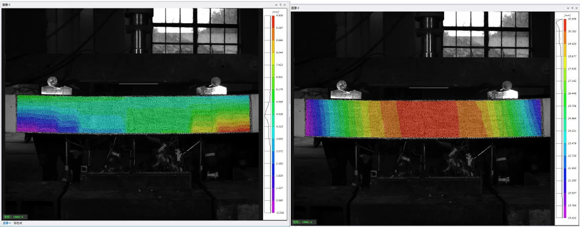
Specimen No. 2 X-Displacement & Resultant Displacement
Characteristics of Strain Field Distribution
During the mid-to-late stages of loading, the maximum principal strain in Specimen No. 2 propagated in a "butterfly" pattern beneath the loading point, with the zone of influence extending to one-third of the beam's width. Tensile strain was concentrated at the center of the beam's soffit, while high-strain bands inclined at 50°–55° formed on both sides; this indicates that the slender beam was subjected to combined flexure and shear, and that these inclined high-strain bands served as a significant precursor to the initiation of shear cracks.
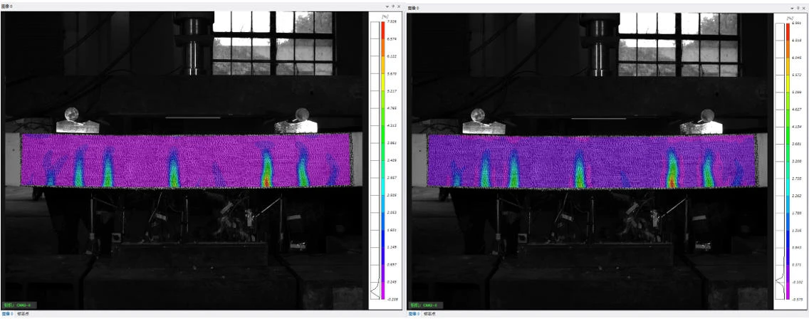
Specimen No. 2: Principal Strain & X-Strain
Characteristics of Displacement/Strain vs. Load Curves
In the elastic stage, the slender beam exhibits lower stiffness, resulting in a flatter slope for the displacement-load curve. Following yield, a distinct plastic plateau emerges, characterized by a displacement increase of approximately 40% alongside load fluctuations of less than 5%. The strain curves reveal three distinct phases: elastic growth, plastic flow, and failure due to instability; a sharp rise in strain at lateral measurement points after yielding confirms the delayed initiation of shear cracks, indicating ample plastic deformation prior to structural failure.
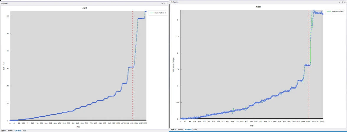
Displacement-strain curve for Specimen No. 2
Crack Evolution Characteristics
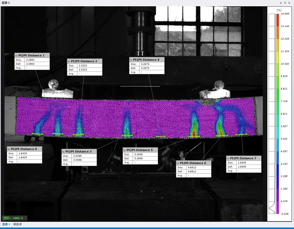
Specimen No. 2 exhibits multi-stage, synergistic crack propagation: primary flexural cracks initiate in the region of peak strain at the beam soffit, followed by the development of secondary shear cracks along diagonal strain bands on both sides. Crack widths increase in a stepwise manner; primary flexural cracks dominate early-stage damage, while the accelerated propagation of lateral shear cracks in the later stages ultimately triggers global failure. Based on DIC displacement discontinuity criteria, the initiation locations and propagation sequence of multiple cracks can be precisely identified, enabling dynamic, full-field reconstruction of the cracking process.
III. Core Application Value of DIC Technology
IV. Conclusions
Based on the XTOP3D XTDIC system, comparative compression tests were conducted on concrete beams with two different cross-sections to investigate the effectiveness of DIC technology in concrete crack identification and reconstruction. The main conclusions are as follows:
1. Traditional monitoring methods are prone to missing micro-damage, have limited monitoring ranges, and struggle to facilitate quantitative analysis. In contrast, non-contact DIC measurement offers full-field, high-precision, and non-intrusive capabilities; it overcomes the limitations of traditional techniques and meets the requirements for refined, full-lifecycle damage monitoring of concrete structures.
2. The two types of beams exhibited distinct failure characteristics: the wide-section beam underwent localized brittle failure, characterized by the rapid propagation of a single through-crack and an absence of significant plastic deformation; the slender beam, subjected to combined flexure and shear, underwent a complete elastic-plastic transition and exhibited failure driven by the stepwise propagation of multiple cracks. DIC technology clearly distinguished the damage mechanisms and failure modes of both beam types.
3. DIC technology is capable of identifying micro-cracks, locating multiple crack sets, and performing dynamic tracking and quantitative reconstruction throughout the entire process. With excellent data precision and continuity, it provides robust support for structural mechanism research, numerical simulation calibration, and in-service safety assessment, demonstrating broad prospects for engineering application.





















