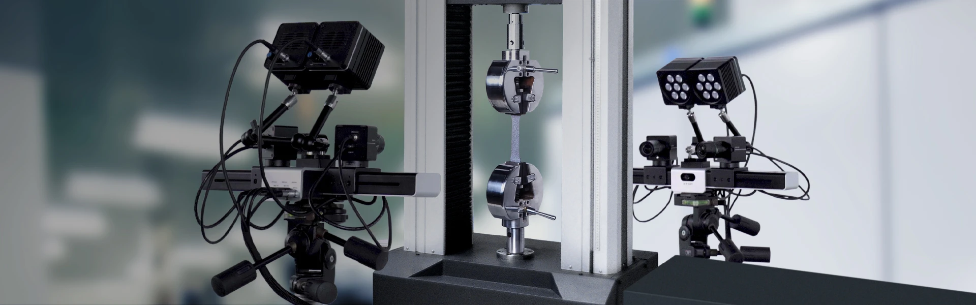
As the scales, performance requirements, and operational environments of subjects such as advanced structures and high-end equipment become increasingly extreme, investigating the mechanical properties and response behaviors of materials under such conditions has emerged as a pioneering frontier for future research.
In particular, achieving breakthroughs in high-precision Digital Image Correlation (DIC) measurement methods for extreme conditions represents both a focal point and a significant challenge in experimental mechanics; it is a crucial technology for uncovering new principles and phenomena in extreme mechanics, as well as a vital entry point for supporting major national projects and addressing key scientific research needs.
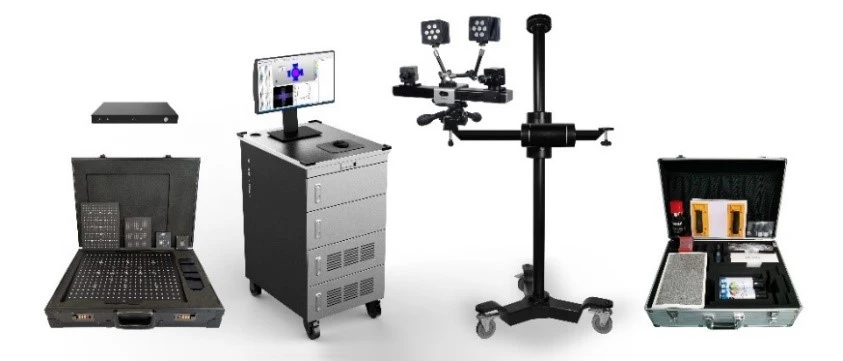
Challenges in DIC Testing Under Extreme Conditions
High Temperature: Image distortion and noise caused by thermal radiation and degradation of speckle pattern quality.
Underwater: Image distortion resulting from light refraction at the water-window-air interface.
High Speed: Complex synchronization and calibration of high-speed cameras; persistent background noise during vibration testing.
Micro- or Macro-scale: Images captured via microscopy at small scales exhibit more complex distortions than those from conventional cameras; achieving a massive field of view (FOV) requires calibrating multiple cameras and using algorithms for image stitching and merging.
Originating from Xi'an Jiaotong University, XTOP3D is one of China's earliest high-tech enterprises dedicated to professional DIC technology research. For over a decade, XTOP3D has continuously invested in the development of algorithms and software modules as well as hardware performance enhancements. By overcoming image distortion and noise interference associated with extreme environments, the company has successfully enabled DIC applications in scenarios such as high-temperature, high-speed, multi-scale, and underwater testing.
1. High-Temperature Environments
In high-temperature experiments, the specimen is typically placed inside a heating device, and the camera captures images through a designated viewing window. The size of this window is usually restricted to avoid compromising the thermal insulation of the heating apparatus.
Acquiring accurate deformation field data using DIC at high temperatures presents three primary challenges:
1) Thermal radiation emitted by the specimen can cause image overexposure;
2) The reliability of the speckle pattern may be compromised; high temperatures can cause speckles to detach due to thermal expansion or degrade due to ablation;
3) Heat haze (thermal turbulence) between the specimen and the camera deflects the optical path, resulting in image distortion.
The XTOP3D XTDIC 3D full-field strain measurement system possesses extensive project experience in high-temperature applications. Reliable, high-precision test data validate the feasibility of DIC testing, enabling full-field strain measurement at temperatures up to 3000°C.
To address the interference of thermal radiation with image acquisition, the system employs blue/ultraviolet lighting, optical filtering, and air knife technology to filter out wavelengths outside the blue/UV range, thereby mitigating the impact of thermal radiation.
Regarding thermal flow disturbances, air knives or fans are used between the heating device and the lens to accelerate airflow and alleviate the heat haze effect.
Furthermore, to enhance the stability of speckle quality, parametric speckle preparation techniques utilizing high-temperature-resistant materials are employed to ensure speckle reliability. Pre-oxidation of the speckles is performed prior to the experiment to minimize adverse effects on displacement field calculations.
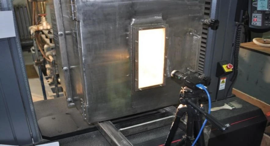
Tensile test of materials at high temperatures
Coupling of Temperature and Strain Fields
DIC testing in high-temperature environments typically employs high-temperature furnaces; however, specific scenarios require the integration of temperature and strain fields for simultaneous measurement.
The XTDIC 3D full-field strain measurement system can be integrated with an infrared thermal imager to simultaneously measure the temperature and strain fields of a specimen in a high-temperature environment.
By combining infrared camera geometric calibration technology and linking the infrared camera's local coordinate system with that of the DIC system, the XTDIC system enables spatial and temporal synchronization for the full-field analysis of temperature and displacement.
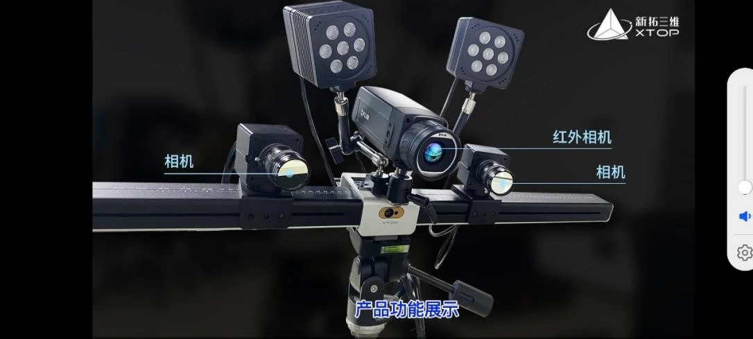
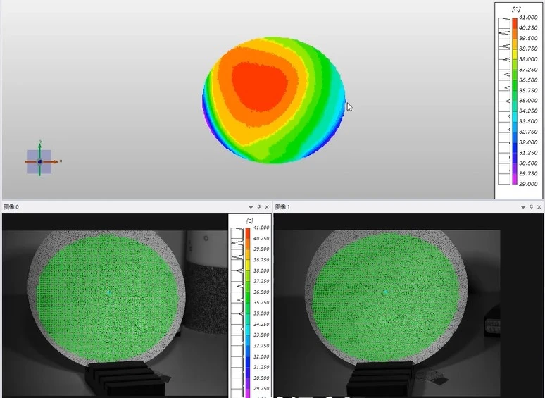
Coupled measurement of temperature and strain fields in alloy sheets
2. Underwater Environment
DIC measurement in underwater environments presents significant challenges, notably complex distortions caused by multiple light refractions. Image distortion is decomposed into two components: refraction-induced distortion and lens distortion.
The XTDIC 3D full-field strain measurement system enhances measurement accuracy for underwater targets by establishing distinct refraction correction models. These models precisely determine the camera's intrinsic and extrinsic matrices as well as distortion parameters, enabling the correction of lens distortion.
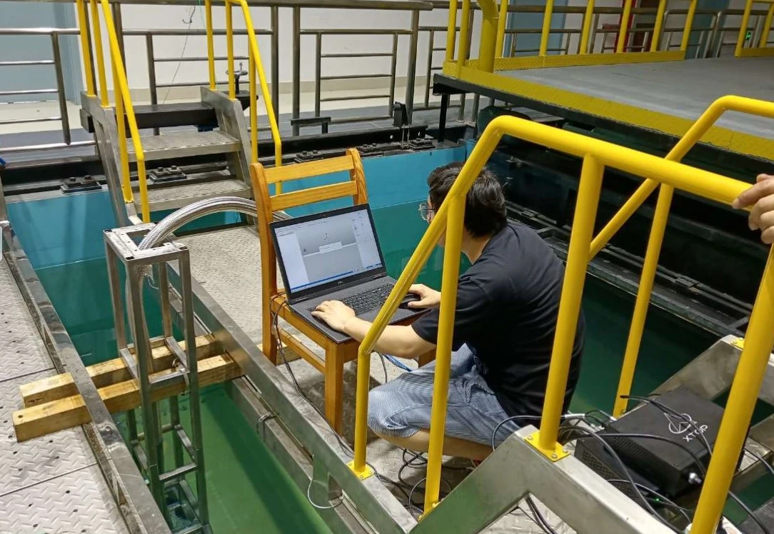
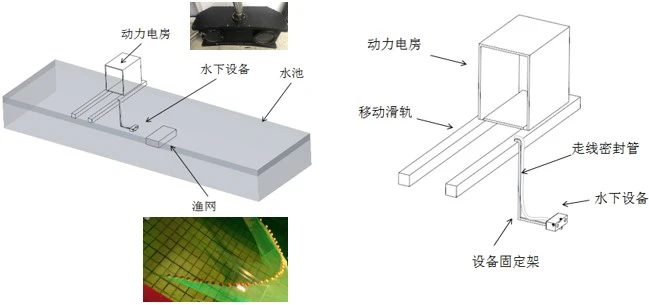
Analysis of Fishing Net Dragging Displacement in a High-Pressure, Sealed Underwater Environment
In controlled laboratory tests, the DIC setup is typically positioned in air, capturing images of the submerged specimen through a viewing window or a transparent container; this allows for precise control of lighting and ensures the water remains clear and free of impurities.
However, in complex environments such as oceans or lakes, the water can obstruct the camera's view, preventing it from capturing a complete image of the underwater structure. Consequently, specialized waterproof housings are used to enclose the DIC cameras in sealed, underwater containers.
3. High-Speed Applications
Advances in high-speed photography have greatly facilitated the observation of transient events, enabling the study of phenomena such as ballistics, explosions, Hopkinson pressure bar tests, and high-speed impacts.
Key challenges in high-speed DIC measurement include the synchronization of two high-speed cameras and issues with unstable lighting. The XTDIC-SPARK 3D high-speed measurement system enables direct control over high-speed camera data acquisition and utilizes laser-assisted illumination to minimize interference with DIC measurement results.
The XTDIC-SPARK 3D high-speed measurement system is widely used in engineering fields involving high-speed impact, vibration, deformation, and motion, allowing for the calculation and tracking of data such as displacement, trajectory and orientation, velocity, and acceleration.
3.1. High-speed motion
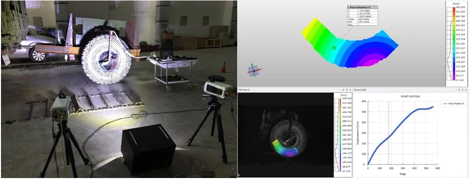
Analysis of Transient Deformation of Automobile Tires During Obstacle Traversal
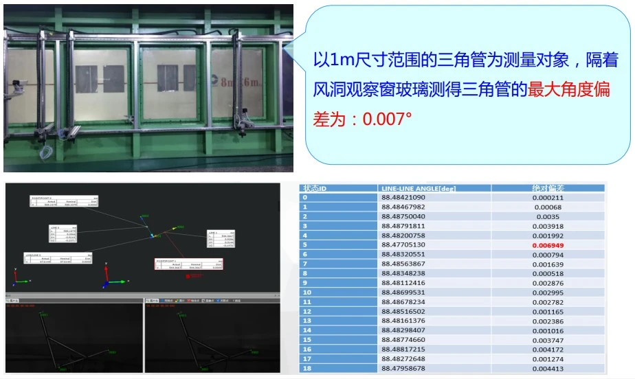
Wind Tunnel Testing – High-Speed Motion and Attitude Analysis
3.2. High-speed impact
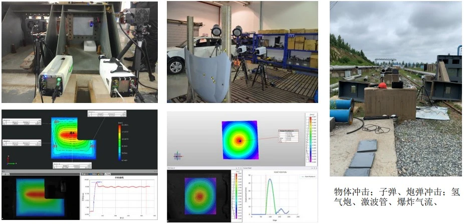
Analysis of Transient Deformation under High-Speed Impact
3.3. High-speed deformation
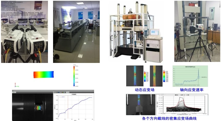
Hopkinsson bar / high-speed tensile dynamic deformation
3.4. Blast Impact
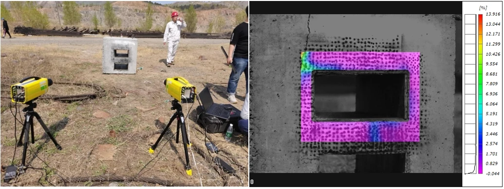
Maximum transient principal strain due to blast impact
4. Macro-scale and Micro-scale
In the field of materials science, observing the microstructure of materials is essential; likewise, the measurement of complex structures is indispensable for the health monitoring of large-scale components.
4.1 Micro-scale
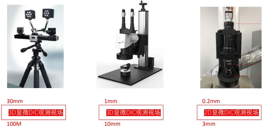
The XTOP3D XTDIC-MICRO microscopic strain measurement system integrates DIC technology with a stereo microscope. Utilizing proprietary DIC calibration and correction algorithms, it analyzes deformation in the stereo microscope's field of view while correcting for measurement errors caused by spatial distortion.
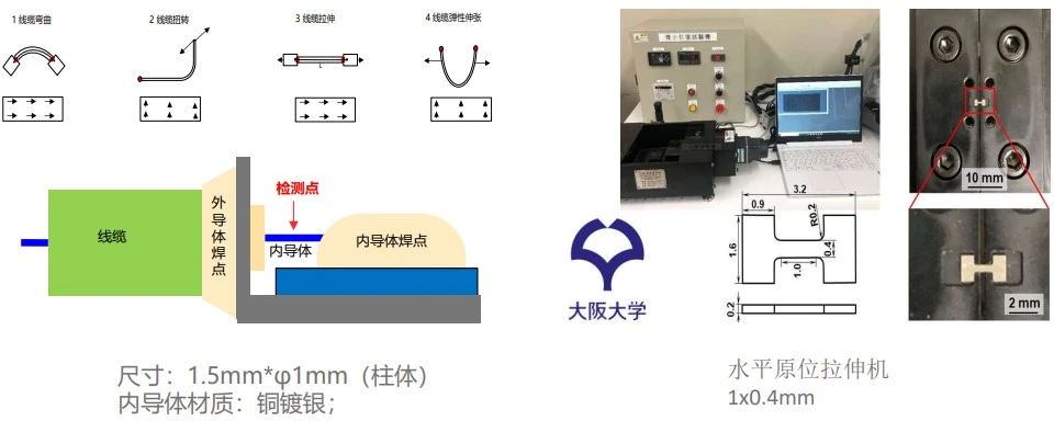
The XTDIC-MICRO system supports integration with various devices—such as environmental chambers, thermal stages, and in-situ testing machines—to enable high-precision strain measurement across diverse temperatures and testing scenarios.
Applications of Mechanics—Forces on Materials
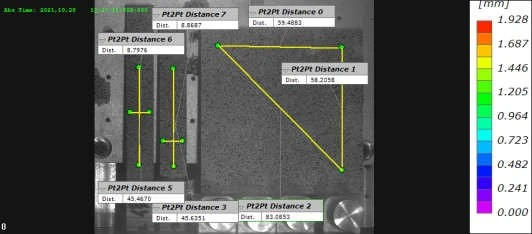
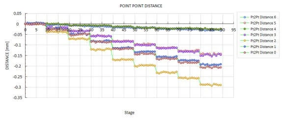
Thermal Applications—Thermal Expansion/Thermal Warpage Measurement
4.2 Large Field of View
When dealing with large objects featuring complex surface geometries, the coverage provided by a standard two-camera DIC setup may be insufficient for comprehensive analysis.
Large-Field Full-Field Strain Measurement
The XTDIC 3D full-field strain measurement system supports a calibration method that decouples intrinsic and extrinsic parameters, effectively addressing the challenges associated with large-field-of-view calibration. To align all images within a single, unified coordinate system for reconstruction, the local coordinate system of one camera can be designated as the primary reference.
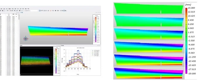
Full-field flapping displacement contour map of an extra-large wind turbine blade (tens of meters in length)
Multi-Camera DIC Solution – 360° Full-Field Measurement
The XTOP3D XTDIC 3D full-field strain measurement system employs a multi-camera DIC configuration utilizing multiple measurement heads. By using pre-calibration to establish a unified coordinate system—or through alignment and frame-by-frame registration—the system achieves coordinate unification across 3D space.
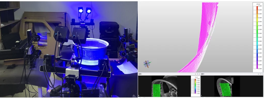
Four-probe configuration—measuring the inner and outer walls of the wheel hub.
Mirror-Assisted DIC Observation
For scenarios involving confined internal spaces and spatially distributed measurement areas, the XTDIC 3D full-field strain measurement system—utilizing mirror assistance and close-range photogrammetry—can unify the coordinate systems of multiple binocular measurement units, enabling the simultaneous measurement of various dispersed surfaces within a structure.
Regarding issues such as camera lens distortion and mirror surface quality, precision compensation is achieved through calibration methods, ensuring high-accuracy measurement results.
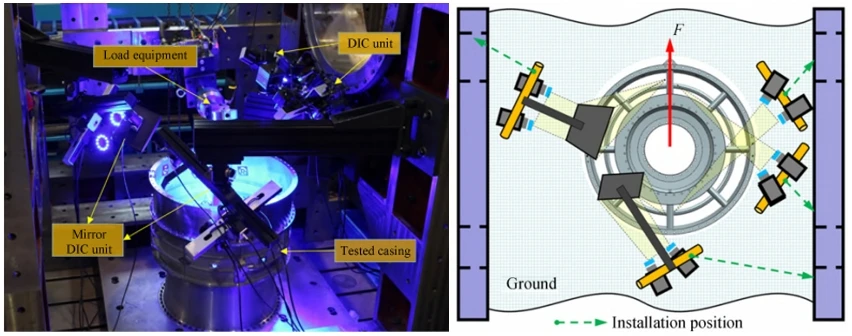
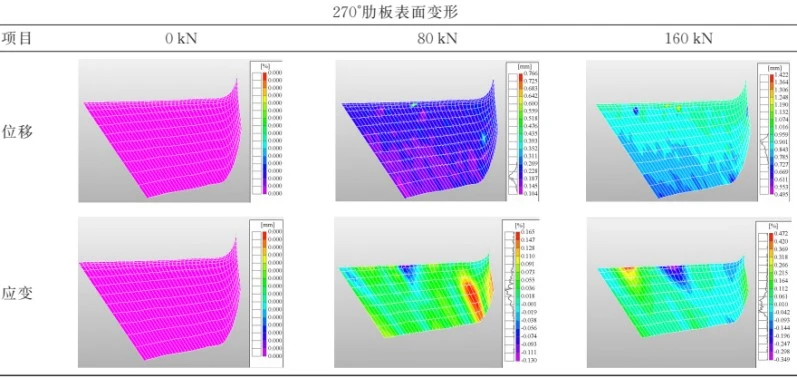
Reflector-based scheme: Synchronous measurement using four probes inside an aero-engine casing.



















 Video Center