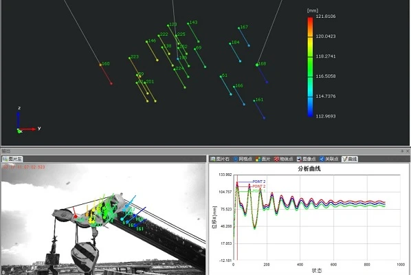
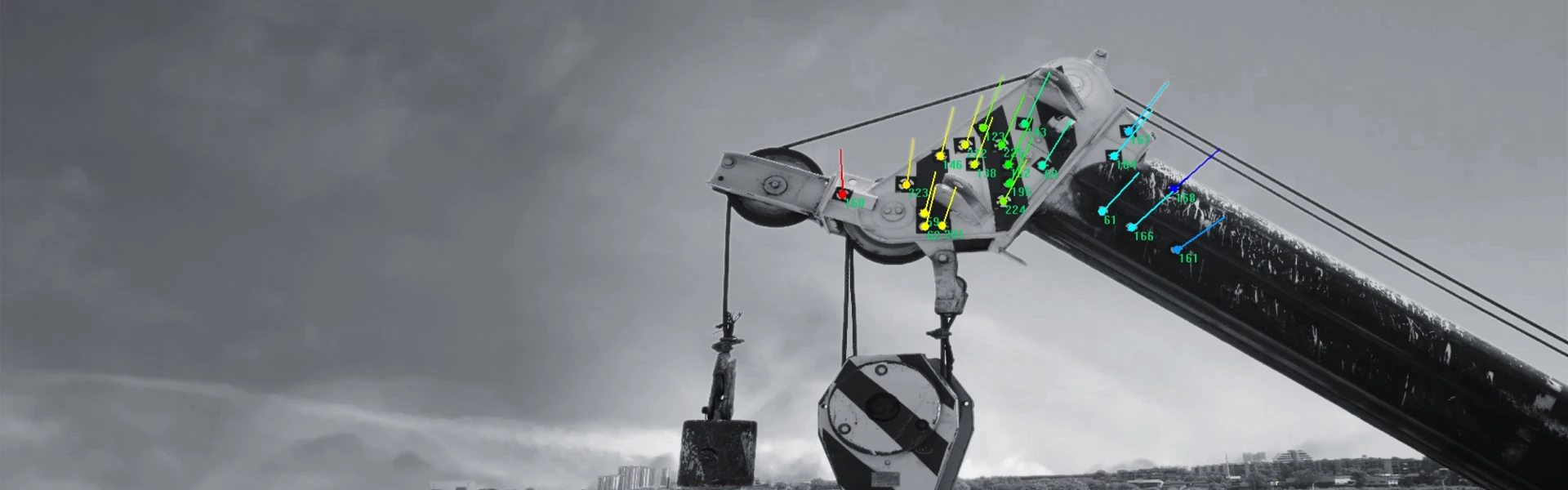
The project focused on measuring the sway displacement of crane booms. The XTOP3D XTDIC system was utilized to measure key load-bearing points on the booms of two cranes operating at different speeds—one low and one high.
1. Marking with Coded Points
First, several coded markers were affixed to the tip of the crane boom; this process took approximately a few minutes.
2. 3D Dynamic Displacement Measurement
To measure the sway displacement of the boom, the XTOP3D XTDIC dynamic measurement system captured data in real-time. By tracking the displacement of the coded markers, the system measured the boom's sway displacement in the direction perpendicular to the boom's plane.
Displacement analysis data for the boom of the first crane operating at low speed
Displacement analysis data for the boom of the second crane operating at high speed
3. Curve Analysis
The difference between the highest peak and the lowest trough observed during the measurement is a key metric. The curves show that during low-speed operation, the differences between the peak and trough values at the three points were 46.08 mm, 44.78 mm, and 43.05 mm, respectively. During high-speed operation, the differences were 76.12 mm, 73.73 mm, and 71.44 mm, respectively. The subsequent minor, prolonged fluctuations indicate that the boom was swaying back and forth around its final stable position.