In the aerospace sector, quality assurance is paramount; even the slightest dimensional defect can compromise quality, necessitating precision inspection of components at every stage of production. Consequently, the industry is prioritizing efforts to enhance inspection efficiency and accuracy, ensure component geometry and dimensions meet design standards, and drive the digital transformation of manufacturing.
Blue-light 3D scanning technology offers a highly efficient and precise solution for measuring and inspecting aerospace structural components, ensuring that product quality and performance meet rigorous industry standards. It enables the inspection of component dimensions and shapes prior to final assembly, thereby guaranteeing assembly precision and allowing for the evaluation of assembly outcomes.
Requirements for 3D Inspection and Assembly Verification
3D Full-Dimensional Inspection
Precision components often feature complex free-form surfaces and intricate structures—such as complex shapes, grooves, mounting holes, and narrow gaps—where traditional contact-based measurement methods often encounter blind spots. Quality control in this context faces three major challenges:
Complex Structures
Intricate features—including curved surfaces, holes, and thin walls—make it difficult for traditional measuring tools to achieve comprehensive coverage.
Strict Tolerances
Critical areas, such as mating surfaces and mounting holes, demand extremely high precision regarding dimensions, positional accuracy, and profile tolerances.
Low Inspection Efficiency
Quality control processes are time-consuming and rely heavily on manual expertise, resulting in poor consistency and high costs.
Why perform virtual assembly?
1. Cost Control
Prevents part damage caused by physical trial assembly (especially for surface-treated or thin-walled components), significantly reducing costs associated with trial assembly waste.
2. Assembly Reliability
Detects potential assembly interference between parts and verifies precise positioning for each component in advance, substantially increasing the first-pass assembly success rate.
3. R&D Efficiency
Enables the simultaneous validation of multiple design options (such as the fit performance of different tolerance zones), thereby shortening the product development cycle.
4. Supply Chain Collaboration
Facilitates digital sharing of assembly validation data across different manufacturing sites, reducing the time required for supplier coordination regarding process adjustments and assembly.
Blue-light 3D scanning solution
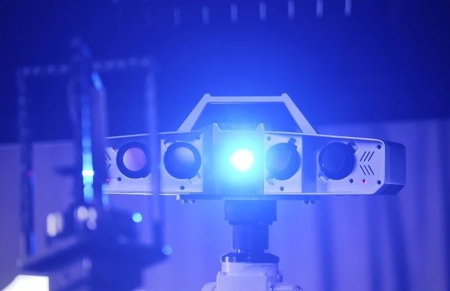
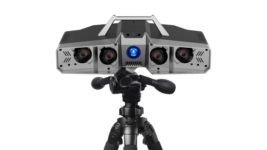
The XTOP3D XTOM blue-light 3D scanner utilizes blue-light fringe projection technology to efficiently capture 3D data from complex workpieces. It accurately reproduces intricate surfaces and fine details, delivering the precision required for geometric dimensioning and tolerancing (GD&T) analysis and inspection.
By importing 3D scan models—including those of assemblies—into the software, the system automatically aligns coordinate systems using reference markers. This enables the analysis of gaps and interferences between components, effectively replicating the actual assembly conditions.
Full-dimensional 3D inspection of blades
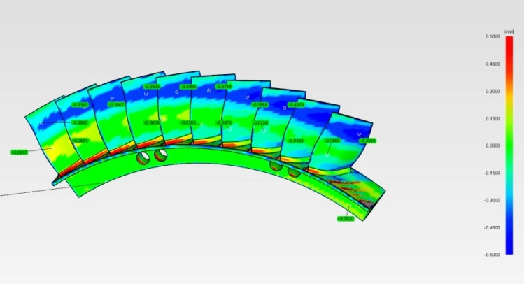
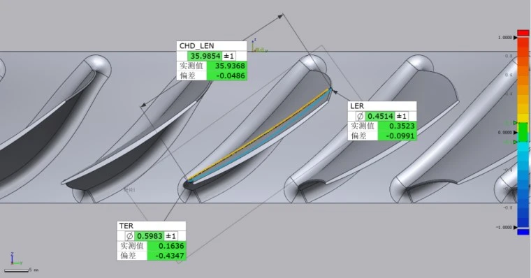
The XTOM blue-light 3D scanner performs 3D scanning, inspection, and analysis on the airfoil profiles of precision-cast blades. It analyzes critical dimensions such as chord length, leading edge, and trailing edge, and directly generates full-dimensional inspection reports, thereby enhancing inspection efficiency and reliability.
-
Perform GD&T analysis on dimensions such as blade chord length, leading-edge diameter, and trailing-edge diameter.
-
Align the scanned model with the CAD model to enable full-dimensional 3D inspection.
-
Generate overall deviation data and annotations to help improve assembly accuracy.
-
Analyze the assembly fit between parts to facilitate product design iteration and optimization.
3D Inspection and Analysis of Plastic Parts
The XTOP3D XTOM blue-light 3D scanner performs multi-angle scanning of plastic parts to generate high-quality 3D data models in real time. By importing the scanned 3D model and the original CAD design into inspection software, the system enables full-dimensional 3D inspection of the plastic parts; it precisely measures critical parameters—such as hole locations, mounting surfaces, cylindricity, and positional deviations—to intuitively determine whether the product meets design specifications.
-
Mating surfaces and mounting holes: Inspect the flatness, parallelism, and positional accuracy of mating surfaces, as well as the hole diameters, hole spacing, and coaxiality of mounting holes.
-
Thin walls and fine features: Check the uniformity of thin-wall thickness, as well as the dimensional accuracy and integrity of fine features.
-
Curved surfaces and fillets: Analyze the profile accuracy of curved surfaces, fillet radii, and transition quality.
-
Tolerance analysis: Determine whether the plastic parts meet specifications based on design tolerance requirements and calculate the rate of parts falling outside tolerance limits.
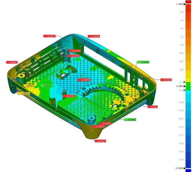
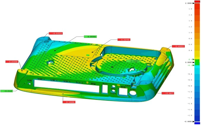
Blue-light 3D scanning and assembly verification
Traditional manufacturing processes rely on physical trial assemblies, requiring iterative testing and time-consuming optimization using physical prototypes; a single assembly verification can take days, and it is difficult to quantify assembly gaps or interferences or to optimize the process.
By utilizing XTOM blue-light 3D scanning technology, the generated 3D data models can be used for assembly verification. This allows for the early validation of assembly compatibility, the detection and avoidance of assembly interferences, and the prevention of downstream rework. Furthermore, archiving these 3D scan models provides valuable support for future quality traceability, product iteration and upgrades, and process optimization.
Virtual assembly of the drone connecting housing
The XTOP3D XTOM blue-light 3D scanner was used to scan the drone's battery compartment and battery connection housing, capturing complete, high-quality 3D data models of the physical components; these scan data were then compared against the original digital models to generate color-coded deviation maps.
Based on the virtual assembly results and precise dimensional data, the design-optimized 3D models were utilized for 3D printing to rapidly produce the physical housings for the drone and battery connection, thereby realizing the optimized assembly structure design.
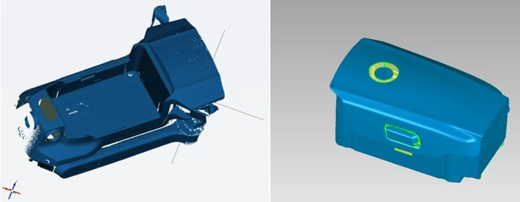
Physical 3D scan data model
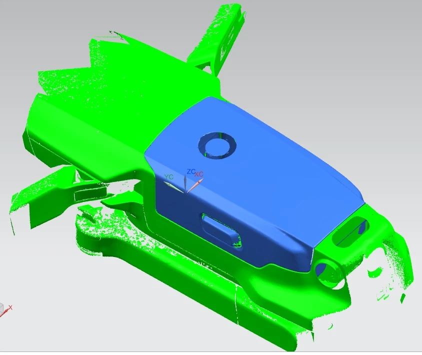
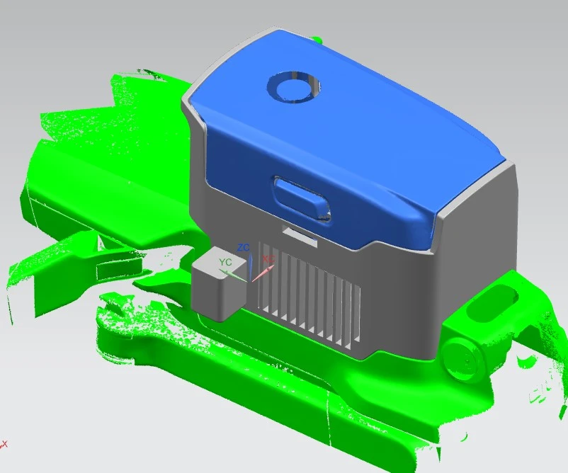
Virtual assembly results for the drone and battery housing
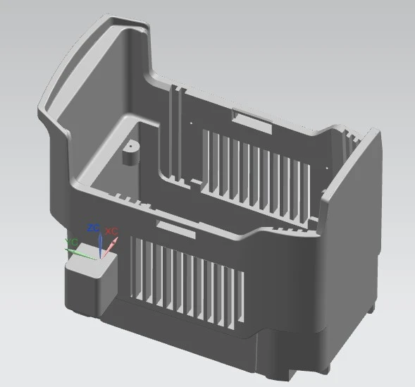
The intermediate gray connecting housing was designed based on the virtual assembly results.
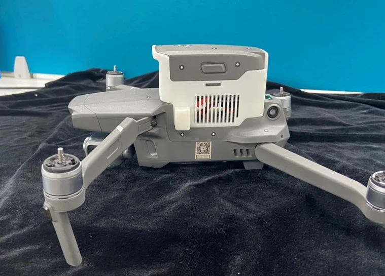
Assembled view of the 3D-printed gray housing
Assembly Analysis of Gears and Gear-Mounting Shafts
The gear and mounting shaft to be assembled were scanned using the XTOP3D XTOM blue-light 3D scanner to acquire STL mesh data. By aligning the gear and the mounting shaft with their respective CAD models based on reference features, a virtual assembly of the gear was achieved.
-
Establish reference data based on the fit between the gear and the mounting shaft, and align this with the CAD model;
-
Perform a virtual assembly analysis of the gear using the aligned CAD model;
-
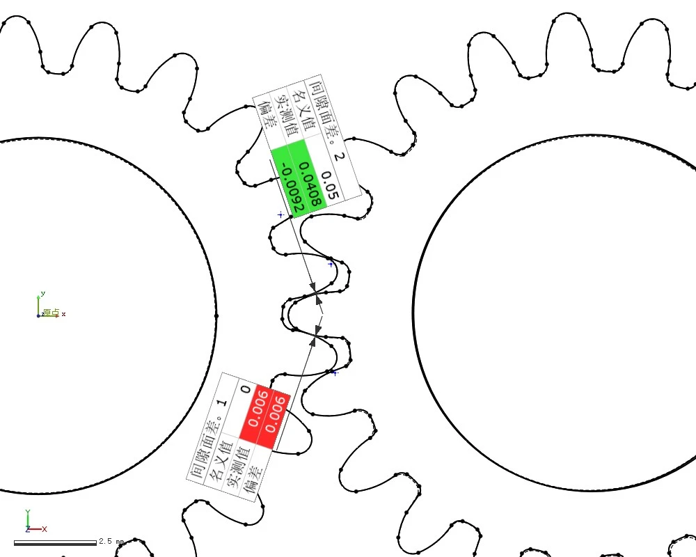
Use the clearance and flushness function to calculate the minimum clearance at the gear mesh point;
-
Extract 2D cross-sections at any position along the Z-axis to analyze the minimum clearance.
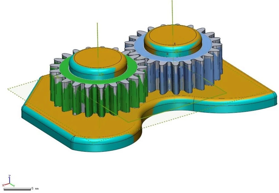
The XTOM blue-light 3D scanner enables rapid, high-precision acquisition of part geometry data, ensuring that the part's shape and dimensions meet design standards.
Gear assembly clearance/offset 1: The theoretical meshing distance is 0, the actual measured value is 0.006, and the difference is +0.006 mm; clearance/offset 2: The theoretical meshing distance is 0.05, the actual measured value is 0.0408, and the difference is -0.0092 mm.