The rapid development of metro rail systems relies on a supporting equipment manufacturing industry; consequently, 3D scanning technology is increasingly valued for its role in the development and quality control of metro car bodies, structural components, and molds. Given the large size and complex free-form surfaces of metro car bodies and structural parts—which pose challenges for traditional measurement methods regarding space requirements and inspection speed—XTOP3D’s blue-light 3D scanning solution enables high-quality, efficient scanning, modeling, and inspection.
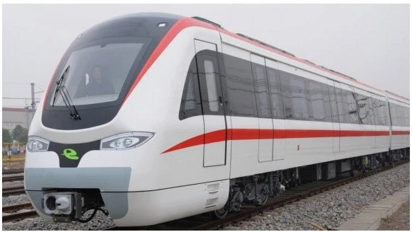
01. Tolerance Inspection of Subway Car Bodies
Subway car bodies consist of thin-walled sheet metal stampings. Compared to machined parts, the dimensional inspection of these stampings presents specific challenges:
1. Complex and irregular shapes make positioning, supporting, and clamping difficult.
2. Low rigidity and high ductility make them prone to deformation and measurement errors during inspection.
3. High precision is required for form and position tolerances; the complex assembly requirements of subway cars make it difficult to fully verify dimensional compliance.
Regarding quality inspection, dimensional deviations in thin-walled sheet metal stampings primarily originate during the stamping stage. Key factors include positioning variations between stamping steps, the manufacturing precision of the stamping dies, die wear, and fluctuations in stamping press parameters.
Therefore, the first article produced from the die must undergo tolerance inspection, followed by periodic spot checks during mass production. By using the XTOP3D XTOM blue-light 3D scanner to scan the stamped sheet metal parts, a complete 3D digital model is generated. This model is then compared against the original CAD data to analyze deviations and determine whether they fall within tolerance limits, ultimately helping to improve the manufacturing precision of the sheet metal stampings.
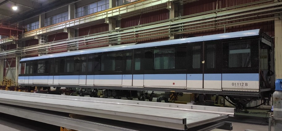
On-site scanning of subway car body stamped parts
Given the massive dimensions of the subway car body, the scanning process employed a measurement strategy combining an XTOM blue-light 3D scanner with global photogrammetry. Global photogrammetry was first used to capture spatial reference points on the car body, followed by the use of the XTOM blue-light 3D scanner to acquire 3D data for areas with complex contours, ultimately generating a complete 3D data model of the car body.
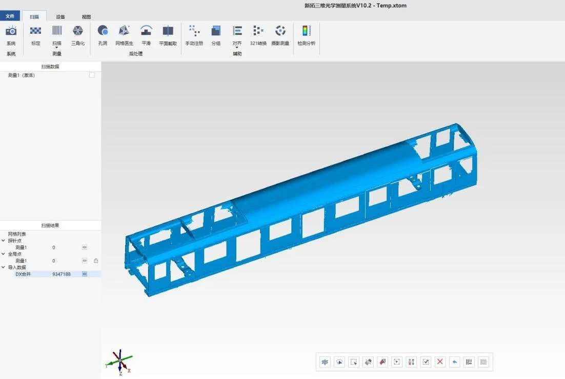
Output STL data upon completion of scanning.
Following the production of the subway car body, the mounting holes for components such as doors and windows must meet established standards, with overall dimensional deviations kept within design tolerances. By comparing 3D scan data against the original CAD model, the degree of deformation is calculated to inform future product improvements.
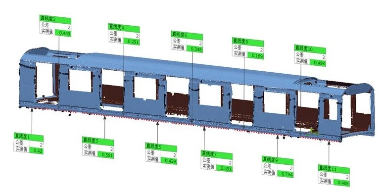
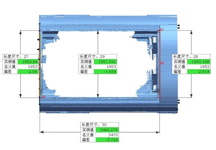
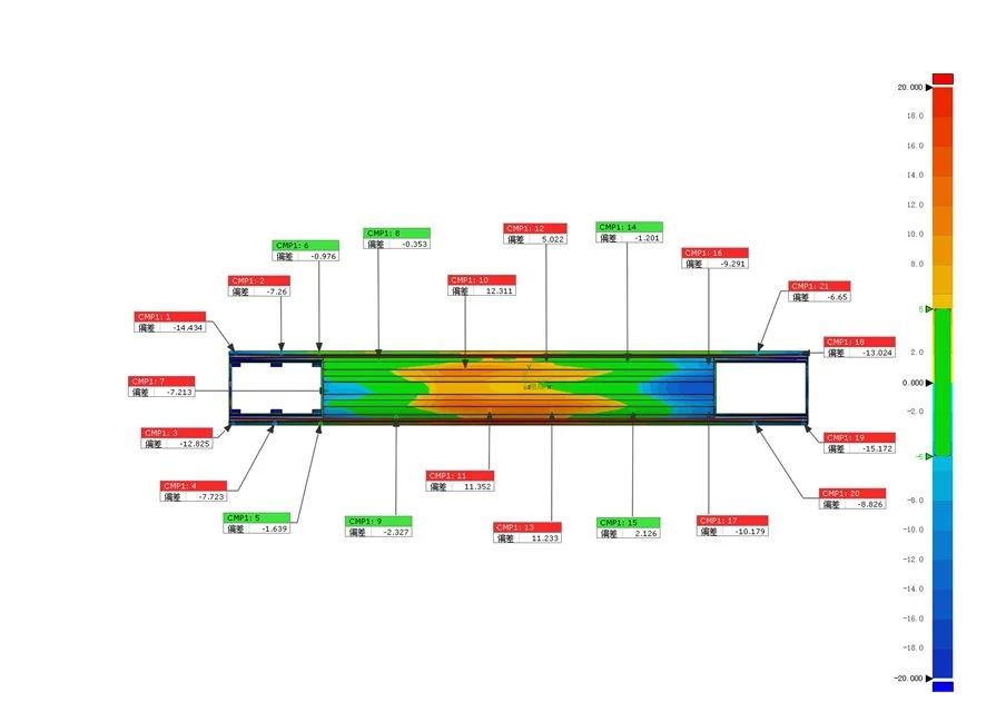
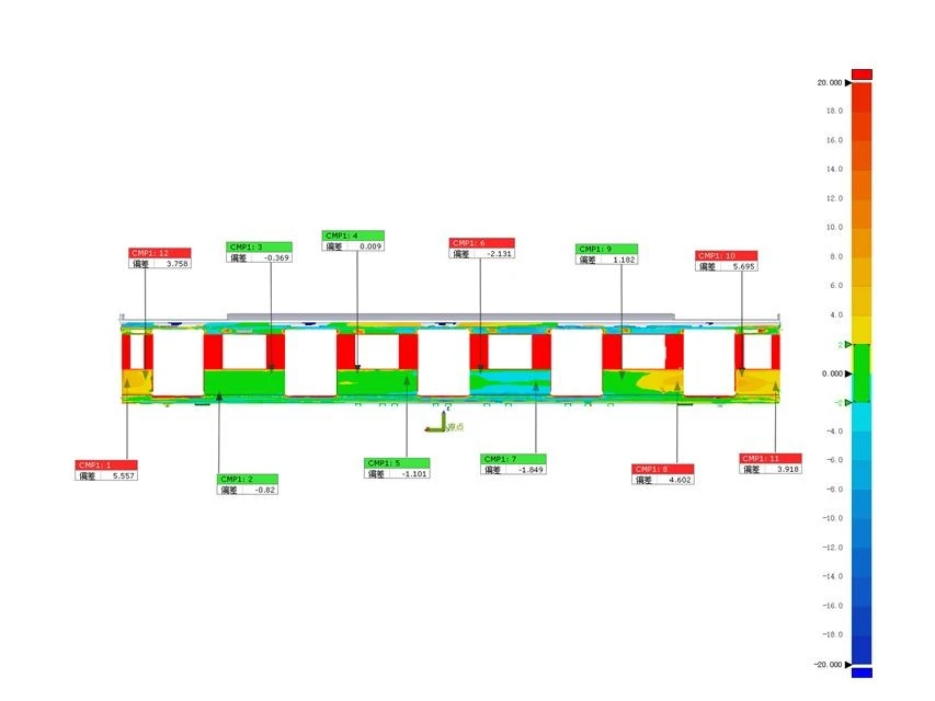
3D Digital Model Comparison Inspection Results
02. Reverse Engineering of Subway Light Structural Components
The design of subway light components generally falls into two categories: components with regular surfaces, designed by defining curves through parameters; and components with irregular surfaces, characterized by complex, contoured profiles featuring various protrusions and indentations.
Forward design for irregular surfaces involves long development cycles and high costs. Given the complex structural shapes of subway lights, manufacturers face the challenge of accurately converting these components—characterized by numerous surfaces and intricate profiles—into CAD models.
Reverse engineering enables the rapid conversion of physical objects into CAD models. Whether applied to replication, improvement, or innovation, this process leverages and builds upon existing technologies.
Lightweight design for subway light components is no exception; achieving this goal relies heavily on reverse engineering. By using an XTOM blue-light 3D scanner to scan the 3D profiles of these structural components, manufacturers can rapidly acquire complete 3D data models. These models can then be processed and edited to generate digital surface models in universal formats.
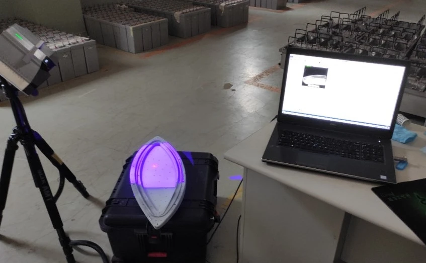
XTOM 3D scanning software outputs STL data.
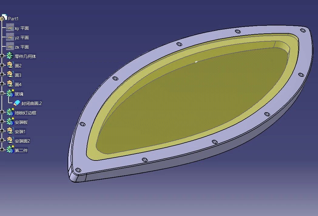
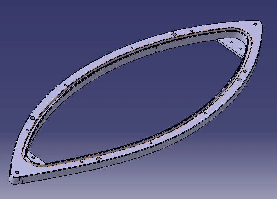
Scan to obtain the STL file, then import it into 3D software to facilitate rapid reverse modeling.
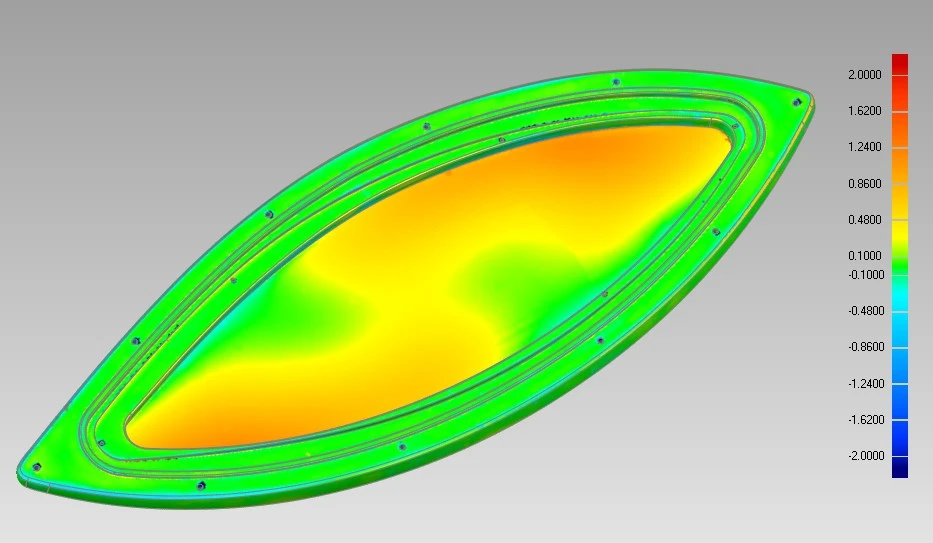
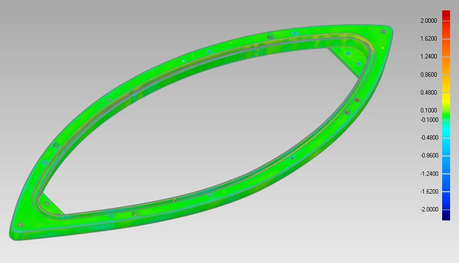
Comparison Report: Scan Data vs. Model
Today, 3D scanning technology is widely used for quality inspection of components and molds for vehicles such as subways and trains. Whether for inspecting curved surfaces and hole positions, or for new product development and lightweight structural design, the XTOM blue-light 3D scanner is the preferred solution. XTOM 3D structured-light scanners provide accurate 3D data for product design, quality inspection, assembly, and production sampling in the manufacturing and production of rail transit equipment.