I. Project Background and Application
Turbine blades are among the most critical components of an aero-engine; they are made from specialized materials and are costly to produce. Engine performance depends heavily on the design and manufacturing quality of the blade profiles. As quintessential examples of components featuring free-form surfaces, their curvature, manufacturing precision, and quality directly determine the engine's propulsion efficiency and safety.
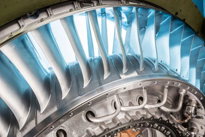
3D dimensional inspection of turbine blades is a highly challenging task that requires the ability to measure specific features, sharp edges, root geometries, and cooling holes. Traditional measurement methods suffer from drawbacks such as long inspection cycles, the risk of contact-induced damage, and the inability to capture full-field dimensional data. Leveraging advantages such as non-contact operation, high precision, and full-field digitization, XTOP3D’s XTOM stationary blue-light 3D scanning technology has become an indispensable tool for modern blade quality control, finding applications in:
Full-dimensional inspection of new products: Ensuring design geometric accuracy meets standards.
Re-certification of reworked blades: Evaluating wear, deformation, and repair effectiveness.
Reverse engineering and mold validation: Accelerating new product development and mold maintenance.
In-process quality monitoring: Tracking critical dimension variations to optimize manufacturing processes.
II. Measurement Difficulties and Challenges
Complex geometric features: free-form surfaces, twist angles, thin-walled structures, and cooling film holes (micron-scale).
Micro-features and recesses: areas such as dovetail roots and tip shrouds present accessibility challenges.
Weld inspection complexity: welds involve irregular curved surfaces, making it difficult to assess overall uniformity; precisely locating defects in the transition zone between the weld and the blade substrate is challenging.
Profile and assembly accuracy: parameters such as blade curvature and parallelism require calculation based on complete profile data; traditional single-point measurements yield insufficient data, resulting in significant errors.
III. Blue-light 3D scanning solutions
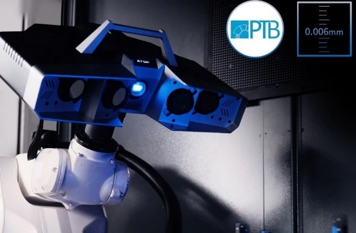
The XTOP3D XTOM stationary blue-light 3D scanner focuses on capturing high-precision data from small-to-medium-sized measurement areas. It accurately detects minute defects and weld textures, making it perfectly suited for inspecting complex free-form surfaces and irregular weld geometries.
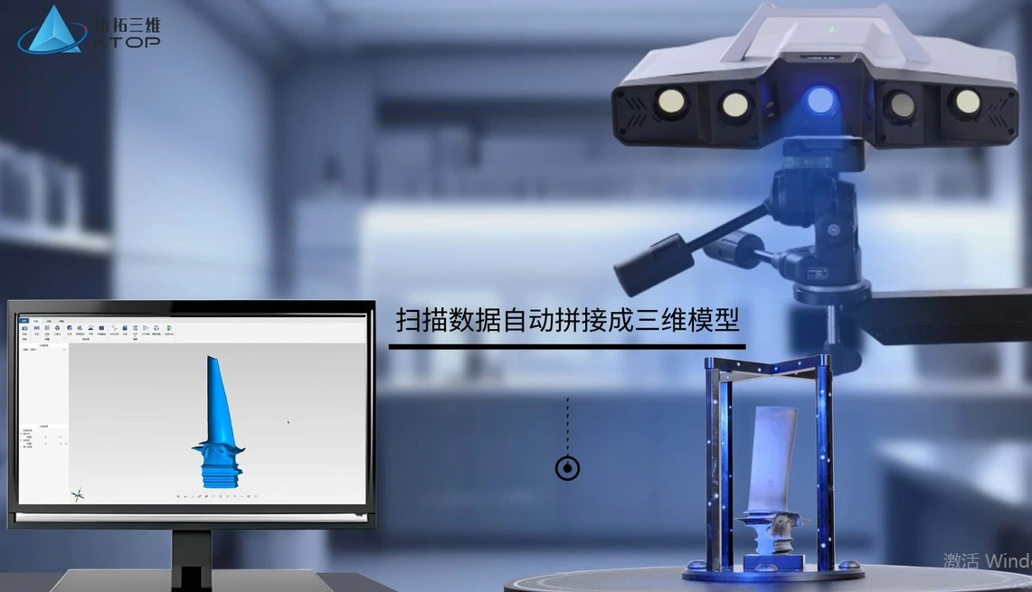
1. Uses modular fixturing for positioning to scan the blade surface, weld seams, and critical profile areas in a single pass, ensuring no measurement blind spots;
2. Employs software for automatic noise reduction and data completion, followed by quantitative analysis of surface flatness and the detection of defects such as cracks and pits;
3. Assesses weld seam uniformity and locates defects like porosity and lack of penetration; verifies profile curvature, parallelism, and critical dimensions, delivering comprehensive and precise data.
IV. Visual Inspection Facilitates Traceability Optimization
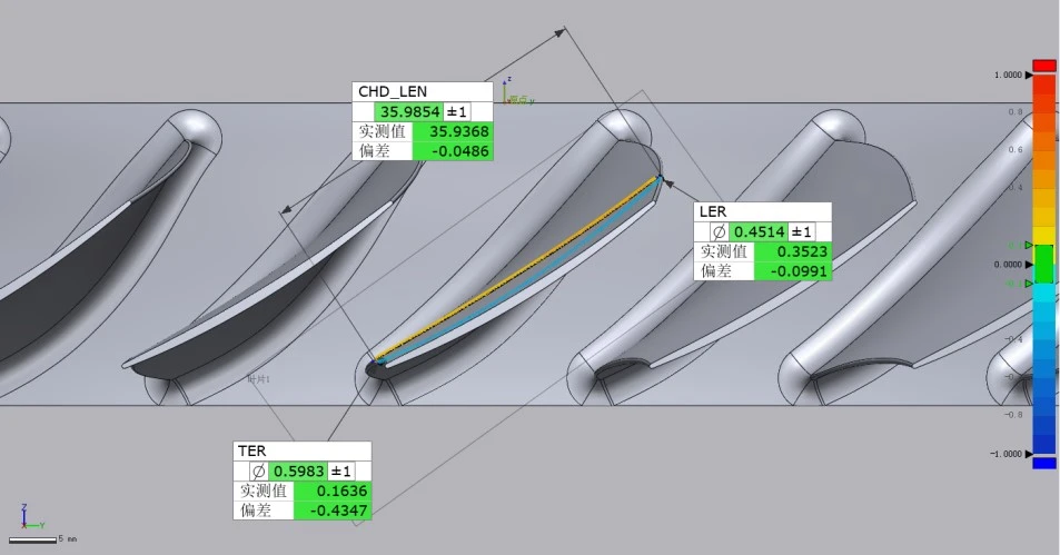
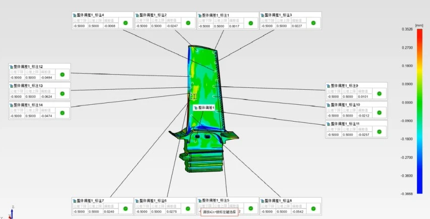
XTOP3D X-INSPECT 3D inspection software enables one-click alignment with CAD models and generates full-field deviation color maps. It automatically extracts key parameters—such as chord width, twist angle, leading/trailing edge radii, and wall thickness (via point cloud offset analysis)—and intuitively displays the locations and magnitudes of deviations, providing data support for quality traceability and process optimization.
1. Full-dimensional inspection
Utilizing multi-angle blue-light fringe projection, a high-density point cloud of the blade—covering all curved surfaces and microstructures—is acquired within five minutes. A full-field deviation color map intuitively displays areas that fall outside tolerance limits.
2. Airfoil profile accuracy
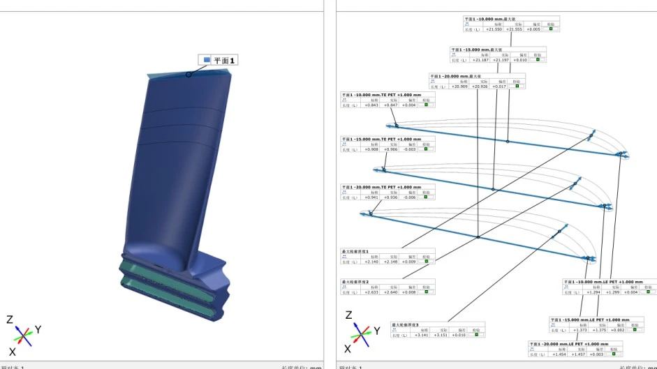
Measure the chord width, twist angle, and leading/trailing edge curvature radii of the airfoil cross-sections. Extract key cross-sections along the blade span, automatically align them with the theoretical CAD model, and calculate the normal deviation between the actual profile and the design (such as aerodynamic efficiency loss caused by distortion of the suction side profile).
3. Edge point and edge circle inspection
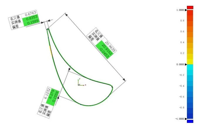
The leading and trailing edges are thin; conventional contact probes are prone to wear and cannot achieve precise positioning. Blue-light 3D scanning technology, combined with sub-pixel edge extraction algorithms, identifies the edge profile and fits the leading-edge radius (R-value).
4. Wall thickness uniformity analysis
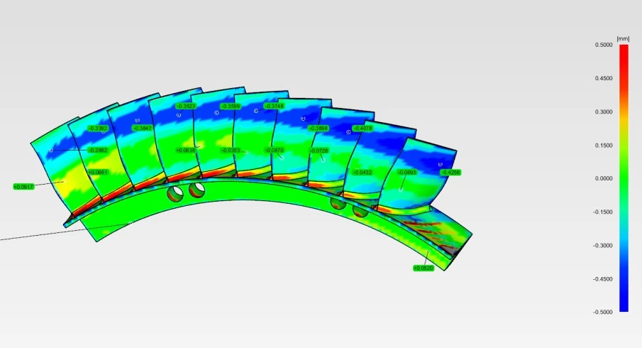
By generating a thickness distribution map, areas at risk of cooling failure (such as blade tip regions with local wall thickness <0.25 mm) are identified; the blade wall thickness Cpk value is analyzed to provide early warnings regarding casting shell deformation.
5. Airfoil cross-sectional shape and positional tolerance
Dovetail installation angle: ensures assembly precision between the blade and the rotor disk.
Blade tip radial position: determines engine airtightness; involves point cloud fitting to identify the highest point of the blade tip.
Film cooling hole positional accuracy: critical for cooling airflow distribution; involves identifying the center coordinates of the small holes.
Cross-sectional shape analysis: compares the center-of-gravity offset across sections (reflecting torsional deformation) and calculates the area moment of inertia to evaluate resistance to centrifugal loads.