Changes in thickness strain during sheet metal deformation serve as criteria for forming limits and are widely applied in methods such as maximum thinning rate, thickness-based criteria, and gradient criteria.
Forming Limit Diagrams (FLDs), constructed using limiting strains, are commonly used to determine the extent of deformation a specific material can withstand under conditions of stretching, bulging, or combined stretch-bulging.
There are generally three methods for determining FLDs:
1. Theoretical calculation. This involves analytical modeling based on various tensile instability criteria to predict the onset of necking and fracture; however, due to the limited applicability of each criterion, discrepancies often exist between calculated and experimental results.
2. Numerical simulation. This can partially replace theoretical calculations to derive material forming limit curves; however, a key challenge lies in incorporating appropriate criteria into the simulation, and the accuracy of the results depends heavily on the operator's experience.
3. Experimental determination. This involves measuring limiting strains and constructing material FLDs under laboratory conditions using standardized tests. It yields the most realistic and reliable FLDs and is currently the most widely used approach.
The XTOP3D XTDIC-FLC sheet metal forming limit measurement system employs a full-field dynamic measurement method based on Digital Image Correlation (DIC). It processes strain data from the frame immediately preceding specimen fracture to obtain limiting strains across various strain paths. These values are plotted on a coordinate system with major strain on the vertical axis and minor strain on the horizontal axis; the system then connects the limiting strain points to generate the Forming Limit Diagram.
Traditional measurement techniques combined with digital image processing methods are used to automatically calculate the deformation parameters of individual circles. However, since these methods process grid images projected optically onto a 2D plane, they are subject to measurement errors and suffer from several limitations:
(1) Strain data is acquired offline (using industrial flexible rulers or toolmaker's microscopes), resulting in high operator dependency and low levels of both accuracy and efficiency.
(2) Grid-based strain measurement methods require a significant amount of manual work for grid application and offer only moderate accuracy.
(3) Measurements can only be taken at the final forming stage, making it difficult to dynamically monitor the deformation process; furthermore, it is challenging to ensure experimentally that the final state corresponds exactly to the forming limit—the point where local necking first appears on the specimen surface.
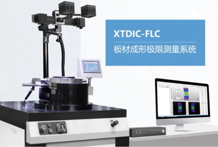
The XTDIC-FLC sheet metal forming limit measurement system offers a dynamic, real-time testing solution. It enables the observation of every instant during the forming process, facilitates practical testing and validation of material formability, and allows for comparative analysis against finite element simulation results.
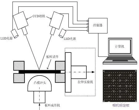
Schematic diagram of FLC experimental setup – DIC hardware components
Dynamic Real-Time Testing—FLC (Forming Limit Curve) Test
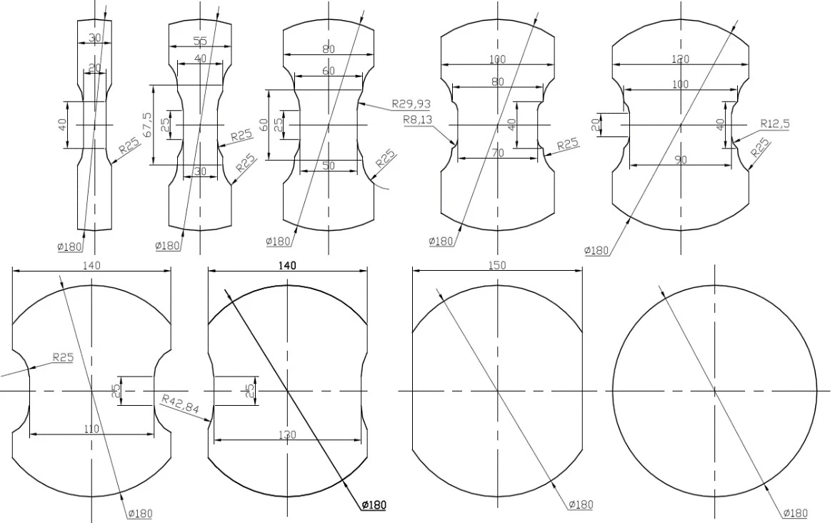
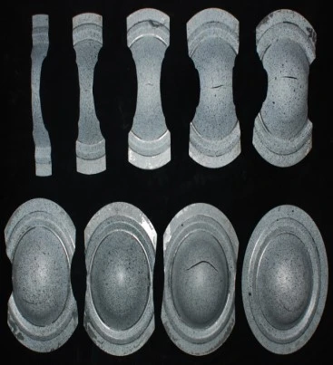
Testing is conducted in accordance with the ISO 12004-2:2008 (or GB/T 24171.2—2009) standard. Nine types of specimens are subjected to sequential stamping, and the full-field strain distribution is calculated. Crack paths and cross-section line orientations are defined to extract data at the point of fracture; this data is then fitted to determine and output the final limiting strain values for the sheet metal in its formed state.
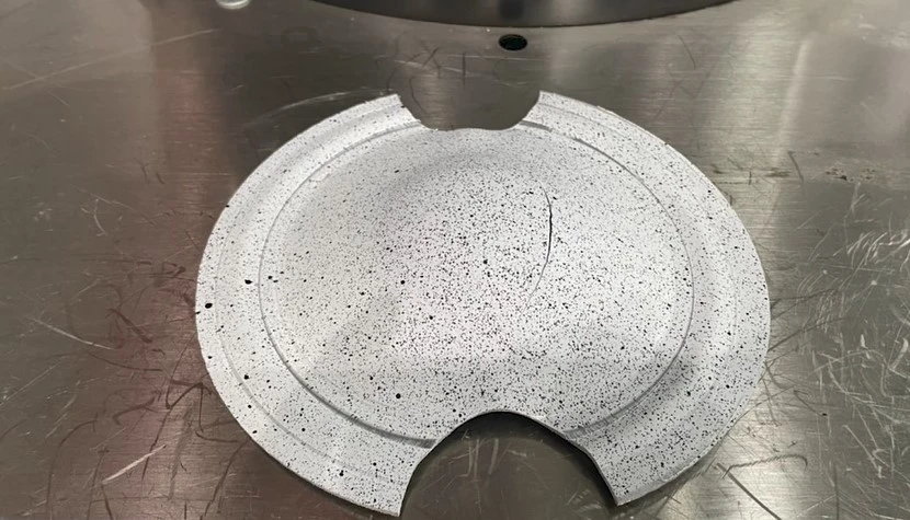
Stamped specimen
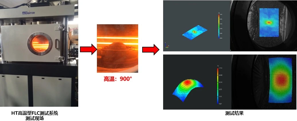
Dynamic Real-Time Testing—High-Temperature Sheet Metal Forming Limit Testing (FLC)
When paired with a high-temperature sheet metal forming machine, the XTDIC-FLC sheet metal forming limit measurement system enables stamping analysis and high-temperature thermal processing research (e.g., on high-strength steel sheets) at forming temperatures of up to 900°C.
Dynamic Real-Time Testing—FLC Forming Limit Testing for Automotive Sheet Metal
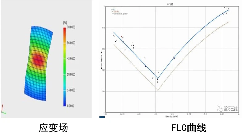
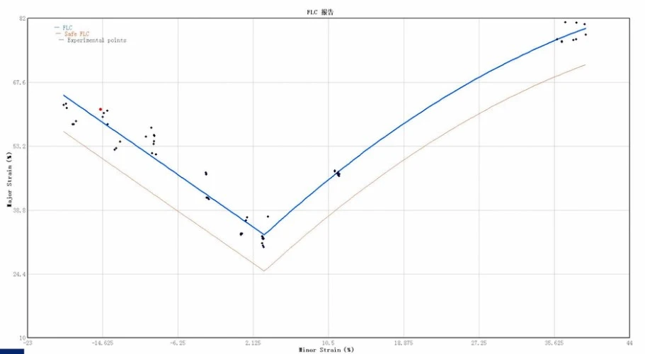
Using the XTDIC-FLC sheet metal forming limit measurement system, the limiting major and minor strains of automotive aluminum alloy sheets are measured under various strain paths, quantitatively revealing the Forming Limit Curve (FLC) under specific stamping conditions.
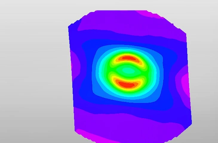
Surface profiles and strain distributions of the specimen under different deformation states
Forming Limit Diagram for Automotive Sheet Metal
Stamped specimen
The sheet metal forming limit strain measurement method based on Digital Image Correlation (DIC) not only measures strain at the final forming stage but also enables rapid, intuitive measurement of surface strain distribution across the specimen throughout the entire forming process.
The XTDIC-FLC sheet metal forming limit measurement system overcomes the limitations of traditional strain measurement methods—such as difficulties in repositioning, complex and time-consuming procedures, and the inability to perform in-situ measurements—thereby offering an effective solution to the challenges of measuring forming limit strains in sheet metal.