Background
With the rapid development of the new energy vehicle industry, higher standards have been set for the forming quality of lightweight vehicle bodies. As aluminum alloys increasingly replace low-carbon steel to achieve weight reduction, the accurate and efficient determination of the Aluminum Alloy Forming Limit Curve (FLC) has become a critical step in evaluating material formability, predicting failure, and optimizing stamping processes.
Traditional grid analysis methods for measuring forming limits (FLD/FLC) suffer from significant drawbacks, including their destructive nature (requiring grid etching), low resolution, sparse data points, high labor and time costs, and the inability to monitor the deformation process in real-time.
Based on Digital Image Correlation (DIC) technology, the XTOP3D XTDIC-FLC sheet metal forming limit measurement system offers higher precision, broader applicability, and more convenient data processing capabilities. It has increasingly become the mainstream measurement technology for FLC testing, perfectly meeting the demands of modern scientific research and intelligent manufacturing for data-driven insights and real-time monitoring.

DIC Technology Application
The XTOP3D XTDIC-FLC sheet metal forming limit measurement system integrates Digital Image Correlation (DIC) and binocular stereo-vision technologies. Working in conjunction with a cupping testing machine, it automatically captures sequential video images of sheet metal deformation during the test. By tracking speckle patterns on the object's surface, the system enables dynamic measurement of 3D coordinates, displacement, and strain during the forming process, ultimately generating the Forming Limit Diagram (FLD) or Forming Limit Curve (FLC) through further data fitting and calculation.
This system is widely used in universities and research institutions for process-related testing—such as assessing the forming performance, plastic limits, and ductility of sheet metals—providing a robust basis for analysis and design optimization.
Key advantages of applying DIC technology to FLD/FLC analysis:
1. Non-contact, full-field measurement: Captures strain data across the entire specimen surface, overcoming the limitations of sparse sampling inherent in grid-based methods.
2. High spatiotemporal resolution: Detects transient and localized deformation (such as the onset of necking) with precision far exceeding that of traditional methods.
3. Simultaneous in-plane and out-of-plane displacement measurement: Enables concurrent analysis of instability phenomena, such as wrinkling.
4. Visualization of dynamic processes: Allows real-time observation of the entire deformation process, facilitating an intuitive understanding of failure mechanisms.
Sheet Metal Stamping and Forming Test Procedure
Specimen Preparation:
Prepare strip specimens of varying widths in accordance with standards (such as ISO 12004-2 and ASTM E2218), covering strain paths ranging from uniaxial tension to equibiaxial tension.

Create a high-contrast, highly random speckle pattern uniformly across the deformation zone of the specimen.

Test Equipment Configuration:
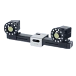
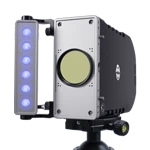
XTDIC-FLC Sheet Metal Forming Limit Measurement System: Two high-resolution, high-speed cameras; a high-brightness, uniform light source; and a stable mounting stand with a vibration-dampening platform.
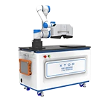
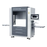
Forming Equipment: Sheet metal forming testing machine (cupping test setup).
Synchronous Triggering: Synchronized data acquisition between the XTDIC-FLC system cameras and the testing machine's load/displacement signals.

Data Acquisition:
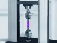
A series of hemispherical punch bulge tests are conducted using specimens of varying widths.
A dual-camera DIC system synchronously records the entire bulging process at a sufficiently high frame rate to ensure the deformation process is clearly captured.
Load-displacement/time data from the cupping testing machine are recorded synchronously.

Real-time Visual Monitoring of Sheet Metal Forming
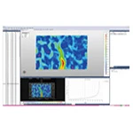
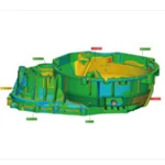
Dynamic display of full-field strain distribution: DIC software performs real-time calculations and visualizes data such as maps of major strain, minor strain, and thickness reduction rates on the specimen surface.
Intuitive visualization of the deformation process: Displacement and strain maps are generated, clearly illustrating material flow and the accumulation and evolution of strain.

Early Defect Detection:
Necking Monitoring: Real-time detection of zones with a sudden increase in local strain (strain concentration bands), serving as a direct indicator of the onset of necking and rupture.
Wrinkling Monitoring: Real-time visualization of sheet surface undulations using out-of-plane displacement fields measured via DIC, enabling precise identification of the location and severity of wrinkling.
Rupture Early Warning: Advance warning of impending rupture based on the degree and rate of change of strain concentration, prior to the appearance of visible cracks.
Process Traceability: Comprehensive recording of the entire deformation history, allowing for the playback and analysis of the deformation state at any given moment.

Precise Determination of Forming Limit Curves (FLC)
Data Processing Workflow:
Selection of Deformation Stage: For each specimen, select strain data corresponding to the critical moment prior to fracture (typically the point of maximum load or the onset of visible necking).
 using DIC technical analysis.")
Identification of limit points: On the strain map at the critical moment, a series of points are selected along a line perpendicular to the direction of the impending crack, spanning the strain concentration zone (necking region) and the adjacent zone of relatively uniform deformation.
Calculation of limit strains: DIC software is used to calculate the major and minor limit strains corresponding to these points.
Plotting the FLC: The limit strain points obtained from all specimens (of varying widths) are plotted on the strain plane, and an FLC curve characterizing the material's forming limit is fitted to the data.
 using DIC technical analysis.")
 using DIC technical analysis.")
Stamping Process Optimization
Die and Process Design: High-precision FLC (Forming Limit Curve) data enables more accurate prediction of forming risks—such as splitting and wrinkling—in various regions of the part, guiding decisions on die surface design, blank holder force settings, draw bead layout, and more.
Rapid Process Parameter Iteration: The real-time monitoring capabilities of DIC (Digital Image Correlation) technology during the tryout phase allow for:
1. Rapid assessment of how different process parameters (blank holder force, lubrication conditions, forming speed) affect material flow and strain distribution.
2. Immediate identification of potential failure zones (where strain approaches or exceeds the FLC).
3. Quick parameter adjustments based on real-time feedback, significantly reducing the number of tryout cycles and associated costs.
Material Property Evaluation and Selection: Efficient determination of FLCs for sheet metal across different batches and grades, providing an objective basis for material selection and supplier evaluation.
Root Cause Analysis of Failures: In-depth analysis of the root causes of production failures—such as splitting or wrinkling—based on complete deformation and strain path data (determining whether the issue stems from the material, the die, or the process parameters).
Summary
Based on Digital Image Correlation (DIC) technology, the XTOP3D XTDIC-FLC sheet metal forming limit measurement system employs non-contact, full-field, high-precision, and visual measurement methods. It not only enables faster and more accurate determination of Forming Limit Curves (FLC) but also provides real-time insights into material flow, strain evolution, and the onset of defects—such as necking, wrinkling, and fracture—throughout the sheet metal stamping process. This system facilitates the analysis of material forming behavior, precise failure prediction, and the efficient optimization of stamping process parameters, thereby enhancing product quality and reducing R&D and manufacturing costs. Ultimately, it helps drive the sheet metal stamping industry toward intelligent and digital transformation.