With the development of the automotive industry and the maturation of the market, consumer expectations regarding vehicle quality have risen steadily. Issues concerning flow-induced structural vibration and aerodynamic deformation are prevalent in the industry, significantly impacting vehicle fuel economy, comfort, and safety.
Automotive wind tunnel testing facilitates the analysis of vehicle dynamic performance by simulating the deformation characteristics that occur during actual road driving, thereby revealing the vehicle body's stiffness and resistance to wind-induced deformation. Measuring body deformation provides valuable data for optimizing interior noise control during high-speed driving and for analyzing the forces acting on components such as the hood and the wind-induced deformation of doors. Such testing is particularly crucial for verifying whether new, lightweight materials meet design requirements.

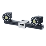
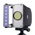
The XTDIC 3D full-field strain measurement system, independently developed by XTOP3D, is based on Digital Image Correlation (DIC) technology. By employing tracking and image registration techniques to accurately measure image changes in both 2D and 3D, the system is frequently used to measure multi-point vibration as well as full-field displacement and strain. It enables precise measurement of instantaneous 3D coordinate changes in automotive components under wind tunnel loading conditions, allowing for non-contact measurement of dynamic deformation—caused by aerodynamic forces—in areas such as car doors, pillars, and hoods. A single marker point can replace displacement sensors in three directions, and the visualized measurement results help R&D personnel better understand the deformation and motion characteristics of the vehicle body.

Limitations of Traditional Testing Methods
At high speeds, a vehicle's surface is subjected to immense aerodynamic loads; even minute structural deformations affect not only aerodynamic performance and wind noise levels but also vehicle handling stability and safety limits. While wind tunnel testing is the primary method for simulating these rigorous conditions, traditional contact-based measurement techniques suffer from several limitations:
1. Pitfalls of Discrete Sampling
Strain gauges and displacement meters offer limited coverage and require complex wiring, increasing the risk of missing deformations in critical areas.
2. Dynamic Response Limitations
Contact sensors struggle to capture high-frequency aerodynamic excitation, while displacement meters (such as LVDTs) are susceptible to additional wind-induced vibration interference in strong airflows.
3. Lack of Spatial Dimensionality
Single-point instruments provide displacement data in only one direction, often failing to yield ideal data for analyzing deflection angles.
4. Data Dimensionality
Data from single-point tests cannot be clearly visualized.
The Importance of DIC Technology Application
Digital Image Correlation (DIC) technology demonstrates irreplaceable value in this scenario:
-
-
Full-field measurement: Overcomes the limitations of single-point measurement by capturing dense deformation data across the entire area of interest (e.g., car doors, hoods, A-pillars, and rear spoilers), revealing deformation patterns and motion characteristics.
-
Non-contact and non-destructive: Requires only the application of markers on the vehicle body; it does not interfere with the structure itself or airflow characteristics, ensuring that measurement results accurately reflect the impact of aerodynamic loads.
-
High-frequency dynamic capture: Powered by high-speed cameras, the system precisely records transient deformation processes (such as vibrations caused by airflow separation) and captures dynamic details.
-
3D shape and displacement: Utilizes stereo vision principles to directly obtain changes in the 3D spatial coordinates of markers and calculate 3D displacement and strain fields, providing comprehensive mechanical data.
-
Quantitative validation and optimization: Supplies critical experimental validation data for CFD simulations, driving the optimization of vehicle body stiffness, the design of aerodynamic packages, and improvements in NVH performance.
Deformation Measurement in Automotive Wind Tunnel Testing
The experiment utilized the XTDIC 3D full-field strain measurement system paired with a 20-megapixel high-speed camera, operating at a sampling rate of 20 fps, to measure the deformation of a vehicle in a wind tunnel at an airflow velocity of 100 m/s.
Deployment of Measurement Points
By affixing markers to the vehicle's surface, it is possible to accurately analyze 3D coordinate changes in the vehicle's structure within the wind tunnel environment.
Additionally, to eliminate rigid-body displacement of the vehicle during testing, reference points affixed to the sides can be used to compensate for the vehicle's overall rigid-body movement, thereby yielding more accurate test results.
Dynamic Data Acquisition
As the wind speed accelerates from 0 to 100 m/s, the high-speed cameras of the DIC system continuously capture images at a sampling rate of 20 frames.
Based on the image data captured by the high-speed cameras, the DIC software performs stereo matching and 3D reconstruction to obtain the 3D coordinates of the marker points.
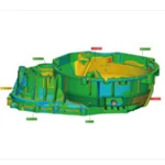
Automotive Wind Tunnel Test Measurement Results
The XTOP3D XTDIC 3D full-field strain measurement system enables the analysis of 3D coordinates, 3D motion and deformation, 3D velocity, 3D acceleration, and 6-degree-of-freedom (6DoF) measurements. By delivering high-precision and highly repeatable results, it helps customers gain deep insight into the dynamic deformation characteristics of components, thereby shortening product development cycles and enhancing efficiency.
1. Data Analysis
Testing of dynamic deformation in the A-pillar area of the left front door frame within the automotive wind tunnel focused on the analysis of three measurement targets. To prepare for the analysis of wind tunnel deformation, the DIC software downsampled the image data to analyze the overall deformation trend and improve processing efficiency.
 technology is used for dynamic deformation measurement of the A-pillar area of the left front door frame in an automotive wind tunnel.")
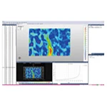
2. Displacement Map Visualization
As shown in the figure, the DIC software can output displacement data for the X, Y, and Z directions as well as the overall spatial displacement. It provides a visual representation of the deformation at the three target points, where arrows indicate the direction of movement, and their length and color represent the magnitude of the displacement.
 technology on the A-pillar area of the left front door frame in an automotive wind tunnel.")
3. Overall Displacement Analysis
The deformation trends at three points in the A-pillar area of the vehicle's front-left door frame are consistent—rising, holding, rising, holding, and then falling—though the displacement values differ.
The total displacement at target point 0 is shown in the figure below:
 Technology to the Analysis of Overall Displacement of the Left Front Door Frame A-Pillar in an Automotive Wind Tunnel")
The total displacement of target 1 is shown in the figure below:
 Technology to the Analysis of Overall Target Displacement in an Automotive Wind Tunnel")
The total displacement of target 2 is shown in the figure below:
 Technology to the Analysis of Overall Target Displacement in an Automotive Wind Tunnel")
4. Z-direction displacement difference analysis
The analysis reveals a slight upward bulging (positive Z-direction displacement) in the A-pillar area of the vehicle's front-left door frame under high-speed airflow.
Using Point 0 as the reference, the Z-direction displacement difference of Point 1 relative to Point 0 is analyzed.
 Technology to the Analysis of Z-axis Displacement of Target Markers in an Automotive Wind Tunnel")
Taking point 0 as the reference, analyze the Z-direction displacement difference of point 2 relative to point 0.
 Technology to the Analysis of Z-axis Displacement of Target Markers in an Automotive Wind Tunnel")
Using Point 1 as the reference, analyze the difference in Z-direction displacement between Point 2 and Point 0.
 Technology to the Analysis of Z-Direction Displacement Differences of Target Markers in an Automotive Wind Tunnel")
By simulating vehicle driving conditions in an aerodynamic wind tunnel and utilizing the XTOP3D XTDIC 3D full-field strain measurement system, dynamic deformation of the vehicle's exterior structure can be analyzed. The process requires only the application of target markers or a speckle pattern to the vehicle surface and the positioning of the DIC equipment at a standard distance before image acquisition and full-field displacement measurement begin. This simple and convenient setup significantly saves time and costs, offering the industry a rapid and efficient testing solution. DIC technology is suitable for a wide range of components; it employs non-contact measurement methods to quickly capture displacement and deformation data. When combined with scientifically sound simulation techniques to analyze the causes of dynamic deformation, it helps address industry challenges such as flow-induced structural vibration and deformation.