As critical load-bearing components of bridge structures, box girders are widely used in modern railway engineering due to their high torsional rigidity, excellent load-bearing capacity, and ease of construction. Currently, a large number of railway bridges built in earlier periods have entered the late stage of their service life, facing safety risks such as structural aging, fatigue damage, and crack propagation.
 Technology to Full-Field Strain and Crack Evolution Analysis of Bridge Box Girders Under Four-Point Bending Loads")
Traditional deformation testing of box girders involves cumbersome procedures, offers limited coverage due to the discrete nature of strain data, and yields results susceptible to human error. To enhance testing efficiency, a research team adopted the XTOP3D XTDIC 3D full-field strain measurement system. Leveraging advantages such as non-contact operation, full-field measurement capabilities, high precision, and superior spatiotemporal resolution, this system serves as an efficient and convenient solution for structural health monitoring and the study of damage evolution in box girders.
 Technology to Full-Field Strain and Crack Evolution Analysis of Bridge Box Girders Under Four-Point Bending Loads")
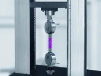
Four-Point Bending Test for Box Girders
Compared to three-point bending, four-point bending creates a zone of uniform pure bending (where shear force is zero) in the central section of the box girder specimen, thereby more accurately reflecting the stress state of the girder under wheel loads. Its advantages include:
Pure stress state: It eliminates shear force interference, allowing for a precise focus on damage caused by bending stress;
Controllable crack localization: The pure bending zone provides a designated area for crack initiation, facilitating the tracking of crack propagation paths;
Multi-level load compatibility: It supports stepped loading-unloading cycles, simulating the cyclic stress history generated by passing trains.
DIC Technology: Applications and Innovations
Traditional strain gauges and extensometers suffer from significant limitations:
Point-measurement limitations: Inability to capture full-field strain gradients and local distortions;
Blind spots in crack monitoring: Difficulty in capturing randomly initiated micro-cracks in real time;
Contact-induced interference: Extensometer installation may alter brittle cracking behavior.
By leveraging the advantages of non-contact, full-field measurement, DIC technology overcomes these bottlenecks, making it the preferred solution for complex damage analysis.
1. Full-field dynamic strain tracking
Obtain real-time full-field strain maps of the pure bending section and quantify strain asymmetry between compression and tension zones;
Identify load transfer paths and principal strain fields to enable full-field crack localization.
2. Quantitative analysis of crack evolution
Utilize sub-pixel displacement algorithms to precisely measure crack width (at the 0.01 mm level), propagation velocity, and fractal characteristics;
Correlate the spatiotemporal evolution of strain localization bands with that of macroscopic cracks.
3. Characterization of residual deformation upon unloading
Assess the accumulation of plastic damage in structural components by analyzing residual strain fields across multiple unloading stages.
Box Girder Four-Point Bending Test Procedure
Test Preparation
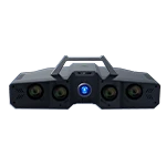
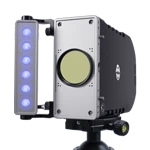
To accommodate a measurement field of view of approximately 4 meters, the XTOP3D XTDIC-CONST-12M 3D full-field strain measurement system is employed for image acquisition. A 12mm fixed-focal-length industrial camera lens is used; characterized by low distortion and high image quality, it ensures measurement accuracy during large-format image capture.

Experimental setup for image acquisition using DIC technology
Experimental Procedure
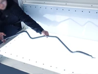
1. Preparation of the speckle pattern on the surface of the bridge box girder: A black-and-white speckle pattern was created using white aerosol paint and black ink applied with a roller.
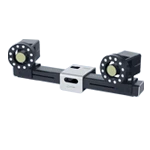
2. Setup of the measurement field: A binocular industrial camera system (XTDIC 3D full-field strain measurement system) was employed. A cross-shaped calibration target was used to perform global calibration of the test surface and the cameras, thereby determining the camera parameters and the world coordinate system.
3. Image acquisition: The binocular industrial cameras of the XTDIC system captured images throughout the experiment. A multi-stage loading process was used, followed by staged unloading.
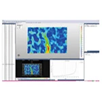
4. Data analysis: The XTDIC analysis software was used to process the data, yielding results such as displacement maps, strain maps, and crack propagation data.
Analysis of Experimental Data
1. The loading process consists of 15 stages, and the unloading process consists of 5 stages. Shown below are the displacement contour maps and displacement curves for the selected points across these 15 loading stages and 5 unloading stages:
 Technology to Full-Field Strain and Crack Evolution Analysis of Bridge Box Girders Under Four-Point Bending Loads")
 Technology to Full-Field Strain and Crack Evolution Analysis of Bridge Box Girders Under Four-Point Bending Loads")
2. To analyze the changes in strain distribution and crack width during the loading and unloading processes, the "point-to-point distance" function of the XTDIC software was utilized. Specifically, the locations of strain concentration within the strain maps—which correspond to the points of crack opening—were analyzed to represent the crack widths. Width measurements were taken at six selected crack opening locations, designated as points 0 through 5.
 Technology")
裂缝云图
 Technology")
Variation in crack width value 0
 Technology")
Variation in the width of Crack 1

Variation in the width of Crack 2

Variation in the width of Crack 3

Variation in the width of Crack 4

Variation in crack width value 5
3. Analysis of the strain contour plots reveals that, in addition to the main crack, there are minor cracks located at areas of strain concentration.

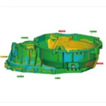
4. The following are contour plots showing the displacement and strain variations of the box girder during the multi-stage loading and unloading process.

Contour plots of displacement changes at loading stages 0–5

Contour map of displacement changes at loading stages 6–11

Displacement contour map at load steps 12–15

Changes in the unloading displacement contour map
The variations in the strain contour plots are less pronounced than those in the displacement contour plots; therefore, four levels were selected for comparison.

Load strain contour map variations

Changes in the strain cloud map upon unloading
This case study successfully applied the XTOP3D XTDIC 3D full-field strain measurement system to a multi-stage loading and unloading test (using a four-point bending configuration) on a decommissioned railway bridge box girder. The system enabled high-precision, non-contact, dynamic monitoring of the full-field strain distribution and the entire process of crack initiation and propagation. The test results not only revealed the patterns of structural damage evolution in the box girder but also provided a scientific basis for assessing the remaining service life of railway infrastructure, formulating maintenance strategies, and making decisions regarding safe operations.
The application of Digital Image Correlation (DIC) technology in the health monitoring of decommissioned structures is shifting from a "supplementary method" to a "core tool"; in the future, it is poised to play an increasingly significant role in sectors with stringent safety requirements, such as railways, bridges, aviation, and nuclear power.