In the incremental pressing process, a feeding mechanism coordinates the delivery of discrete explosive charges into the projectile casing, where a screw-driven ram compresses each charge at a preset pressure to complete the loading cycle automatically.
Consequently, the amount of explosive flowing into the projectile body depends largely on the material's flowability. Excessive flowability can compromise the charge density, whereas poor flowability necessitates more pressing cycles; in the latter case, fewer granules are subjected to higher compressive loads, causing a rapid rise in the charge's temperature and significantly increasing the process's risk.
To investigate how the flowability of the molding powder affects the adaptability and safety of the incremental pressing process, there is an urgent need for a multi-dimensional, mesoscale analysis system capable of tracking granule motion via dynamic digital speckle correlation. This system must integrate a 3D strain measurement and analysis unit, a microscopic DIC strain measurement unit, a molding/loading apparatus, and a non-contact infrared thermography unit. These components will enable real-time monitoring of the pressing temperature and the analysis of parameters such as flow velocity and bulk density, thereby providing a basis for evaluating the requirements of the incremental pressing process.
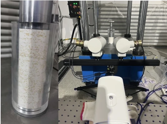
3D Strain Measurement and Analysis Device – Custom Explosion-Proof Enclosure
1. 3D Strain Measurement and Analysis System
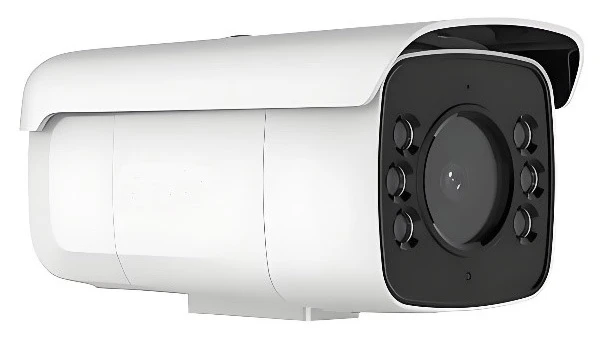
Camera configuration for the XTDIC 3D full-field strain measurement system: equipped with either two 5-megapixel industrial cameras or two 4-megapixel high-speed cameras. The maximum frame rate is 35 fps for industrial cameras and 500 fps for high-speed cameras.
Measurement specifications:
Strain accuracy ≤ 0.01%; displacement accuracy ≤ 0.01 mm; strain range: 0.01%–1000%.
Supports measurement fields of view ranging from 10 mm to 5000 mm; custom field sizes are available upon request.
Field testing of the XTDIC system demonstrated static strain noise (jitter) ≤ 0.01% and displacement accuracy ≤ 0.01 mm.
DIC software analysis confirms a maximum strain measurement range of up to 1000% (operating range: 0.01%–1000%).
Supports input of force signals from testing machines via serial communication or analog signals; capable of calculating material parameters such as Young's modulus, Poisson's ratio, R-value, and N-value.
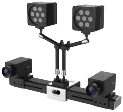
2. Micro-scale Strain Measurement and Analysis System
The XTOP3D Micro-DIC strain measurement system utilizes two 5-megapixel industrial cameras with a maximum frame rate of 75 fps. Paired with an optical stereo microscope featuring a 12.5:1 zoom ratio, it enables a magnification range of 0.8x to 10x.
Measurement Specifications:
Field of view: 2 mm – 10 mm. Strain measurement range: 0.005% – 1000%. Maximum displacement accuracy: 0.005 mm; maximum strain measurement accuracy: 0.005%.
Testing of the micro-scale strain measurement system demonstrates static displacement fluctuation within 0.005 mm and strain accuracy within 0.005%.
The Micro-DIC software supports strain measurements up to 1000%; combined with a strain accuracy of 0.005%, the system achieves a measurement range of 0.005% to 1000%.
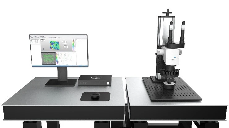
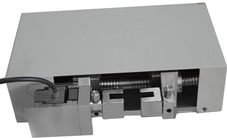
Micro-strain measurement device equipped with an explosion-proof protective cover:
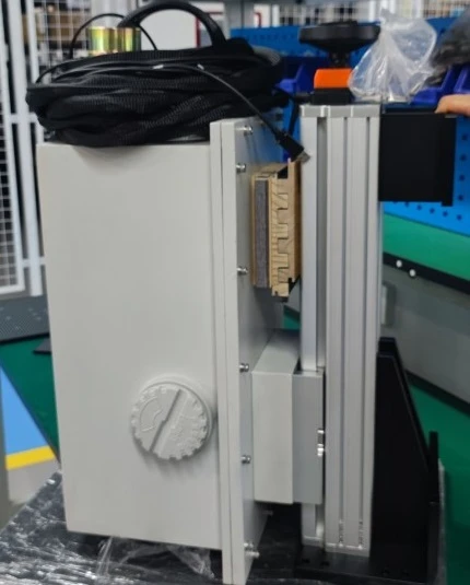
3. Small-scale mechanical testing machine unit
This system is equipped with one explosion-proof, small-scale mechanical testing machine featuring a full-scale force measurement range of 0.4%–100%, a maximum load capacity of 500 N, and an accuracy class of 0.5.
When paired with the XTOP3D microscopic DIC measurement system, it is used for micro-scale steady-state tensile testing; the setup supports a maximum load of 2 kN and meets accuracy class 0.5 standards, with the testing machine maintaining a full-scale force measurement range of 0.4%–100%.
4. Temperature Measurement Devices
This system is equipped with one contact-type multi-channel temperature logger and one non-contact temperature measuring device. The contact-type temperature logger features a resolution of 0.1°C and a measurement range of -50°C to 300°C.
The non-contact temperature measuring device offers a measurement accuracy of 2°C and includes a temperature field recording function. It features a thermal imaging resolution of 640 × 512 pixels, a pixel pitch of 17 μm, and a measurement range of -20°C to +550°C.
Experimental procedure for the multi-dimensional, detailed dynamic analysis of molding powder particles
(1) Place the molding powder particles into the compaction container and position the measuring device at the appropriate location.
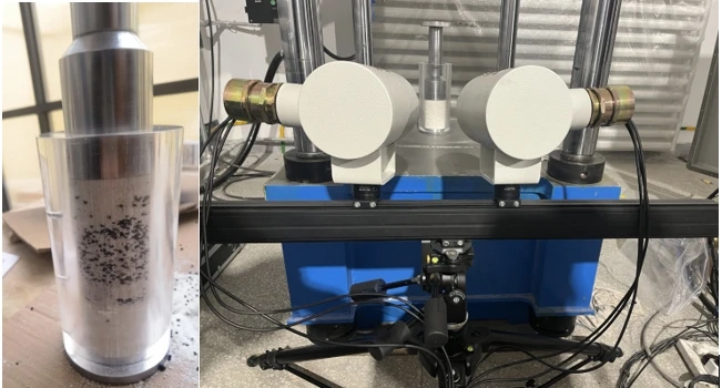
造型粉颗粒与DIC测量装置
(2) The testing machine performs compression while the binocular DIC cameras simultaneously acquire data.
(3) DIC software performs calculations and analysis to obtain data such as displacement fields, strain fields, and temperature.
Analysis of data results from the 3D strain measurement device
The figure below shows the displacement field contour map of the specimen analyzed by the XTDIC 3D strain measurement system. The displacement increases progressively with loading time, and the overall displacement magnitude decreases from top to bottom, consistent with theoretical expectations.
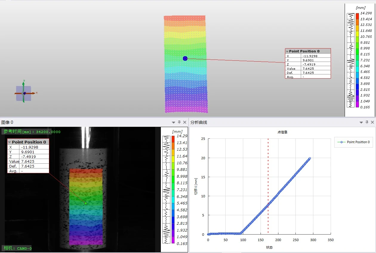
Displacement field contour map
The figure below shows the strain field map obtained from the 3D strain measurement and analysis system; the strain magnitude increases progressively with loading time, and strain concentration appears in localized areas, consistent with theoretical expectations.
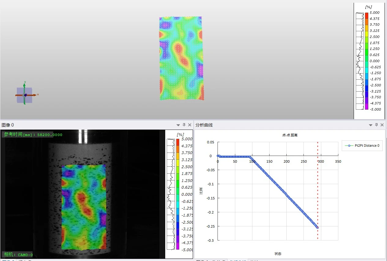
Strain field contour map
Analysis of Data from the DIC Micro-Strain Measurement System
The figure below shows the displacement field maps obtained by the DIC micro-strain measurement system during the loading process. The magnitude of displacement increases progressively with loading time, and the overall displacement decreases from left to right, consistent with theoretical expectations.
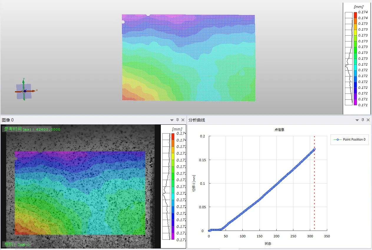
Displacement field contour map
The figure below shows the strain field contour map of the specimen during the loading process, as analyzed by the DIC microscopic strain measurement system; the strain magnitude increases progressively with loading time. The maximum strain is 0.0001 (i.e., 100 microstrain), and a clear, gradual increase in strain is evident.
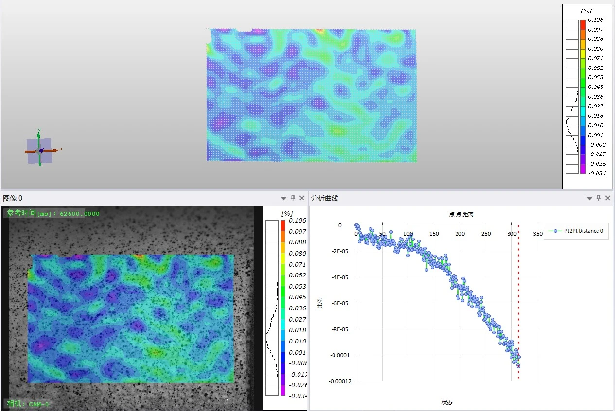
Strain field contour map
Temperature data and temperature field analysis results
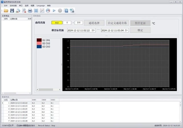
The figure below shows data measured by the contact-type measuring instrument. The software provides a visual display of the temperature data from the three sensors.
Contact Thermometer Data
The figure below shows temperature field data measured by an infrared camera. The software provides a visual display of the temperature field map.
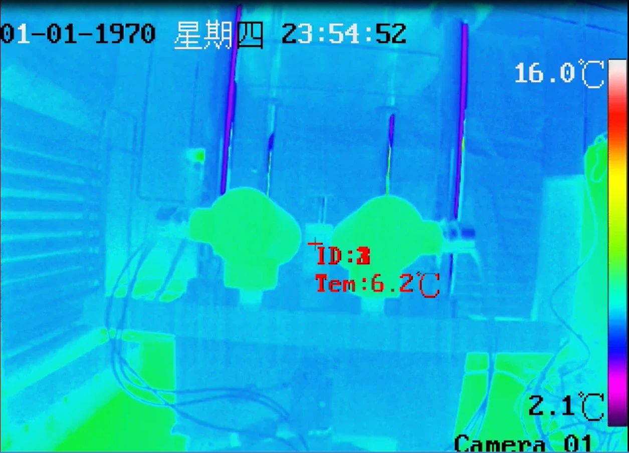
Temperature field contour map
Experimental results demonstrate that the multi-dimensional dynamic analysis setup—utilizing digital speckle correlation to track molding powder particle motion—enables the calculation and analysis of displacement and strain fields during the incremental pressing process. When integrated with a microscopic DIC strain measurement system, this setup allows for the analysis of displacement and strain fields at the micro-scale and real-time monitoring of temperature variations during pressing, thereby facilitating experimental research into the flowability of explosives and incremental pressing processes.





















