Digital Image Correlation (DIC) technology, as a practical and effective tool for measuring surface deformation, is widely used to characterize the deformation and damage behavior of composite materials. Due to their inherent heterogeneity and anisotropy, composite materials exhibit complex deformation patterns under load; the primary advantage of DIC lies in its full-field measurement capability, which reveals the complex and highly localized processes of deformation and damage evolution within these heterogeneous materials—capabilities that traditional point-based measurement methods (such as strain gauges and extensometers) cannot match.
技术用于复合材料变形和损伤表征")
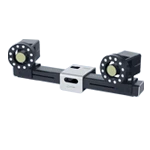
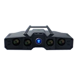
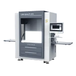
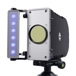
The XTOP3D XTDIC 3D full-field strain measurement system utilizes non-contact, full-field optical measurement technology. By tracking the movement of natural or artificial speckle patterns on an object's surface during deformation, it precisely calculates displacement and strain fields. This enables high-precision, full-field strain measurement on composite material surfaces, accurate identification of points of maximum deformation, and intuitive analysis of failure processes. The system provides essential data support for the performance evaluation and design optimization of composite materials, finding extensive application in both scientific research and engineering fields.
Challenges in Deformation Measurement of Composite Materials
Fiber-reinforced composites consist of distinct constituents and layup configurations, exhibiting anisotropic and heterogeneous characteristics. They possess complex constitutive relationships, and their damage behavior under load is highly complex and stochastic. Beyond material composition, variations in manufacturing processes also influence the resulting microstructure.
Anisotropy and Heterogeneity
Large deformation gradients and highly variable directions place higher demands on speckle pattern preparation and strain calculation algorithms.
Damage modes are diverse and complex.
Phenomena such as matrix cracking, delamination, and fiber breakage can cause local speckle pattern failure or abrupt changes, necessitating specialized handling (e.g., adaptive subsets).
Therefore, when investigating the mechanical properties of fiber-reinforced composite structures, it is crucial to understand and characterize their damage and deformation behavior, requiring the use of advanced testing techniques to monitor the structures under load.
Advantages of Non-contact DIC Measurement Technology
Non-contact, full-field measurement: Captures strain data across the entire specimen surface, overcoming the limitations of sparse sampling associated with grid-based methods.
High spatiotemporal resolution: Captures transient and localized deformations (such as the onset of necking) with precision far exceeding that of traditional methods.
Simultaneous in-plane and out-of-plane displacement measurement: Enables the simultaneous analysis of instability phenomena, such as wrinkling.
Visualization of dynamic processes: Allows for real-time observation of the entire deformation process, facilitating an intuitive understanding of failure mechanisms.
Typical Application Cases of DIC Technology
1. High-Temperature Biaxial Tensile Measurement of Composite Materials
Background: Investigating the effects of high temperatures on the in-plane mechanical behavior (stiffness degradation, strength, Poisson's ratio) and failure modes of composite materials.
DIC Technology Application: Conducting tests within a high-temperature chamber and viewing through a heat-resistant window; pre-calibrating for image distortion caused by thermal radiation and thermal disturbances; and utilizing high-temperature-resistant speckle patterns.
DIC Measurement Results:
High-temperature mechanical properties: Precisely measure the variation of the composite material's elastic modulus and Poisson's ratio with temperature. Capture high-temperature-specific phenomena such as softening and creep.
High-temperature failure mechanisms: Observe the initiation and propagation of matrix-dominated failures (e.g., matrix softening/cracking and interface degradation) at high temperatures, distinguishing them from the fiber-dominated failures observed at room temperature.


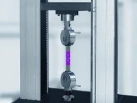
2. Tensile Deformation and Damage Evolution in Fiber-Reinforced Composites (FRP)
Background: Investigation of the fundamental mechanical behavior, as well as the processes of damage initiation and accumulation, in unidirectional, woven, or chopped fiber-reinforced composites under tensile loading.
Application of DIC Technology: High-resolution 2D or 3D DIC measurements performed on the gauge section of the specimens, focusing on fiber-direction, transverse, and shear strain fields.
DIC measurement results:
Localized strain concentration: Identification of highly localized strain concentration zones caused by heterogeneities—such as those between fiber bundles or at fiber-matrix interfaces—which often serve as initiation sites for damage (e.g., matrix cracking, interfacial debonding).
Visualization of damage evolution: Real-time observation of the initiation, propagation, and coalescence of matrix micro-cracks, as well as the formation of the main crack leading to ultimate specimen failure.
Anisotropy characterization: Intuitive visualization of significant differences in strain development across different directions, and quantitative determination of elastic moduli and Poisson's ratios for each direction.
拉伸变形测量")
拉伸变形测量")
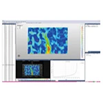
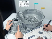
X/Y-direction displacement contour plot
拉伸变形测量")
X/Y-direction displacement contour plot
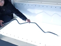
3. Tensile Testing of Composite Structures with Cutouts (e.g., Open-Hole Panels)
Background: To evaluate stress concentrations caused by geometric discontinuities—such as holes or notches (e.g., fastener holes or areas with repair patches)—and their impact on structural strength and damage tolerance.
DIC Application: High-resolution 3D DIC measurement is performed on critical regions surrounding holes or notches, with a specific focus on the strain field at the hole edge.
DIC Measurement Results:
Precise measurement of strain concentration zones: DIC provides the full-field strain distribution around the hole edge, enabling the direct calculation of the Stress Concentration Factor (SCF). This value more accurately reflects real-world conditions—accounting for material anisotropy and damage effects—than theoretical solutions or finite element simulations.
Prediction of damage initiation sites: The region of peak strain concentration (typically located at a specific angle along the hole edge) represents the most likely site for damage initiation (such as matrix cracking or delamination); DIC technology allows for the precise localization of these points.
Monitoring of damage propagation paths: Tracking the progression of cracks initiating at the hole edge as they propagate along specific directions (e.g., fiber orientation or interlaminar planes).
拉伸应变测量")
Strain in the X-direction
拉伸应变测量")
Y-direction strain
拉伸应变测量")
Thickness reduction rate
4. Analysis of Compressive Deformation in 3D-Printed (Additive Manufacturing) Composite Materials
Background: Evaluation of the compressive strength, stiffness, buckling behavior, and interlaminar properties of 3D-printed composites (e.g., continuous fiber-reinforced or short fiber/particle-reinforced thermoplastic matrices).
DIC Application: 2D or 3D DIC measurements performed on the side surfaces of specimens (observing the thickness or printing-layer direction), with a specific focus on the interfaces between printed layers.
DIC Measurement Results:
Impact of Printing Defects: Identification of localized weak points and strain concentrations caused by the printing process (such as voids, lack of interlayer fusion, or fiber orientation deviations), revealing how they trigger overall compressive failure (e.g., micro-buckling, shear failure, or interlaminar cracking).
Anisotropic Behavior: Measurement of significant differences in compressive properties (modulus, strength, Poisson's ratio) between the printing direction (Z-axis) and the in-plane directions (X/Y-axes), characterizing the anisotropy inherent to additive manufacturing.
Visualization of Failure Modes: Clear capture of the initiation and progression of failure modes—such as fiber micro-buckling, matrix shear yielding, interlaminar delamination, or interfacial debonding—under compressive loading.
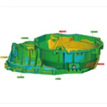
复合材料压缩变形分析")
复合材料压缩变形分析")
X/Y-direction displacement contour plot
复合材料压缩变形分析")
Tensile line strain at opposite corners
With its non-contact, full-field, and high-resolution measurement capabilities, the XTOP3D XTDIC 3D full-field strain measurement system has become a powerful tool for characterizing the complex deformation behavior and damage evolution of composite materials. From revealing micro-scale strain concentration and damage initiation to quantifying macro-scale mechanical property degradation—and spanning conditions from ambient temperatures to extreme heat, as well as materials ranging from traditional laminates to advanced 3D-printed structures—DIC technology provides a wealth of information unattainable via conventional methods. By carefully controlling speckle quality, imaging systems, and computational parameters to overcome environmental challenges, DIC technology continues to play a pivotal role in composite material research and application, significantly enhancing the scientific rigor and precision of material design, performance assessment, failure analysis, and structural optimization.