In the fields of aerospace and high-end equipment manufacturing, the mechanical properties of 3D-printed metal structural components are directly linked to overall system reliability. However, the mechanical performance of these components—particularly regarding localized deformation and the reliability of welded zones—is significantly influenced by process parameters, microstructure, and geometric features; traditional measurement methods struggle to achieve high-precision, non-contact, full-field deformation monitoring.
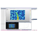
Based on Digital Image Correlation (DIC) technology—an image-matching, non-contact optical measurement method—the XTOP3D XTDIC 3D full-field strain measurement system captures full-field displacement and strain distributions on object surfaces in real time, providing a basis for the quantitative evaluation of the mechanical behavior of hybrid 3D printing and welding processes.
 technique for full-field deformation measurement of 3D-printed metal parts under compression.")
This experiment focuses on 3D-printed metal components with a T-shaped welded structure. By combining stepwise incremental loading with the XTOP3D XTDIC 3D full-field strain measurement system, the study employs Digital Image Correlation (DIC) technology to analyze the longitudinal displacement characteristics of the upper vertical column and the horizontal beam, as well as the evolution of the displacement field at the welded joint. Furthermore, the deformation differences between the standard T-shaped structure and a T-shaped structure with cutouts are compared, providing data to support the design and reliability verification of 3D-printed metal structures.
Experimental Design
1. Specimen Preparation
Two types of typical 3D-printed T-shaped metal components were selected for the study:
Sample 1: A T-shaped metal structural component formed by vertically welding an upper square column to a horizontal crossbeam; the overall dimensions comply with the requirements for tensile/compressive specimens specified in the ASTM E8/E8M standard.
 Technology to Full-Field Deformation Measurement of 3D-Printed T-Shaped Metal Parts Under Compression")
Sample 2: T-shaped structure with cutouts (same material and manufacturing process). A diamond-shaped cutout is designed in the central region of the crossbeam to reduce weight and induce stress concentration, thereby simulating the mechanical response of lightweight structures in practical engineering applications.
 Technology to Full-Field Deformation Measurement of 3D-Printed Metal Parts with Lattice Structures Under Compression")
After the specimen surface is sandblasted, a uniform speckle pattern (matte black and white paint) is applied to ensure DIC matching accuracy.
2. Loading and DIC Measurement Systems
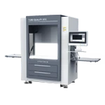
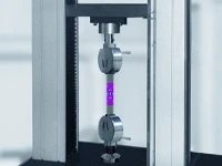
Loading Equipment: A universal testing machine was employed, utilizing a stepwise incremental loading mode with a constant loading rate of 0.1 mm/min to simulate quasi-static compressive loading conditions.
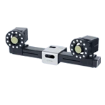
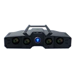
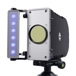
DIC Measurement System: The XTOP3D XTDIC 3D full-field strain measurement system was used, featuring two high-speed industrial cameras (12-megapixel resolution, 25 fps frame rate). Synchronized control was achieved via an external trigger, with the acquisition frequency set to 0.2 Hz (i.e., capturing one image every 5 seconds) to ensure a complete record of key stages during the deformation process.
DIC Measurement Area
Area of interest: The welded connection between the column and the crossbeam (prone to stress concentration).
DIC Measurement and Analysis
Full-field displacement analysis: Extract displacement contour maps (in X [horizontal], Y [vertical], and Z [transverse] directions) for the upper column and crossbeam; plot displacement-time curves for key measurement points (e.g., center of the column top [A], midpoint of the crossbeam [B], and weld edges [C/D]).
Strain analysis: Calculate maximum principal strain contour maps; analyze strain concentration characteristics in welded versus non-welded regions; plot strain-time curves for key measurement points.
DIC Measurement Results and Analysis
Sample 1 – T-shaped metal structural component:
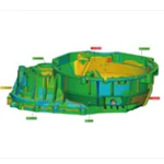
Deformation analysis of the T-shaped structural component
The weld seam is subjected to bidirectional shear and serves as a primary zone of principal strain concentration.
A sudden change in the strain rate at points within the weld zone acts as a warning signal for potential failure.
Red high-risk zone: Weld seam area of the metal structural component.
Base of the weld column—strain gradient indicates a weak zone between printed layers.


X-direction displacement contour plot and point displacement curve


Y-direction displacement contour plot and point displacement curve


Z-direction displacement contour plot and point displacement curve


Contour plot of maximum principal strain and point strain curve
Sample 2 – T-shaped + hollow structure
Deformation analysis of the T-shaped structural component
Column deformation: Predominantly axial compression with uniform strain distribution, consistent with theoretical expectations;
Weld zone response: Subjected to combined bending and shear loads, resulting in abrupt multi-directional displacements and strain concentration;
Crossbeam behavior: Load transfer induces bending and local buckling, with springback occurring at the ends due to the release of constraints.


X-direction displacement contour plot and point displacement curve


Y方向位移云图和点位移曲线

Z方向位移云图和点位移曲线


Transverse and longitudinal linear strains at the ends of the structure
Conclusions and Application Value
Using the XTOP3D XTDIC 3D full-field strain measurement system, high-precision, multi-directional, full-field measurements of the compressive deformation of 3D-printed metal T-structures were successfully conducted, leading to the following conclusions:
Conventional T-structure: The vertical column serves as the primary load-bearing element; deformation in the welded zone is continuous, and strain distribution is uniform, meeting structural reliability requirements.
T-structure with cutouts: The cutouts significantly reduce the stiffness of the horizontal beam, resulting in localized displacement and strain concentrations (increased peak values) and non-uniform strain in the welded zone; consequently, the cutout geometry and welding process require targeted optimization.
DIC technology offers distinct advantages in the full-field analysis of the complex mechanical behavior of 3D-printed metal components. It provides critical experimental data to support lightweight structural design, process parameter optimization, and performance assessment of welded structures, thereby guiding the refinement of welding processes and cutout parameters. It is particularly well-suited for the non-destructive testing and reliability verification of complex metal components.