A precision mold manufacturing enterprise undertook the task of designing and manufacturing electrodes for a high-precision injection mold. This mold is intended for producing plastic parts with complex curved surfaces; the parts feature numerous narrow slots, deep cavities, and intricate textured structures that cannot be achieved through conventional CNC machining, necessitating the use of Electrical Discharge Machining (EDM) to form the mold cavities.
EDM is a material removal process that utilizes the phenomenon of electrical erosion caused by pulsed discharges between a tool electrode and the workpiece. As the tool for this process, the electrode's shape and precision directly determine the final quality of the mold cavity. Thanks to advancements in accuracy, blue-light 3D scanning technology is increasingly being applied to the inspection of molds and electrodes; this ensures machining precision and significantly shortens the product development cycle.
Challenges in Inspecting Electrode Molds
The inspection of electrode mold components faces the following core challenges:
|
Detection challenges
|
Specific manifestations
|
Influence
|
|
The structure is complex and varied.
|
The electrodes are designed based on the mold cavity geometry, incorporating complex features such as narrow slots, deep cavities, sharp angles, and undercuts.
|
Conventional measuring tools cannot access the area for measurement, making data acquisition difficult.
|
|
High precision requirements
|
Electrode dimensional tolerances are typically required to be ±0.02 mm, with a profile deviation of ≤0.03 mm.
|
Difficulty in controlling the discharge gap affects mold precision.
|
|
Multi-electrode correlation detection
|
A single mold requires the coordinated machining of multiple electrodes, and positional consistency must be ensured across them.
|
It is difficult to evaluate the overall fit accuracy through discrete inspections.
|
|
Low detection efficiency
|
Traditional CMM inspection of individual electrodes is time-consuming, resulting in long batch inspection cycles.
|
Affects production takt time and increases inspection costs.
|
|
Discharge gap verification
|
The spark gap between the electrode and the designed surface profile (typically 0.05–0.15 mm) must be verified.
|
Requires precise comparative analysis against the CAD model.
|
Blue-Light 3D Scanning Inspection Solution
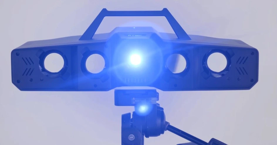
Following a technical review and solution assessment, the company selected the XTOP3D XTOM blue-light fringe projection 3D scanner for the inspection of electrode molds. Utilizing blue-light narrow-band projection technology combined with high-resolution industrial cameras, the system effectively handles the complex surface characteristics of graphite electrodes. Its measurement accuracy meets the ±0.02mm tolerance requirements for the electrodes, providing a reliable data foundation for verifying discharge gaps.
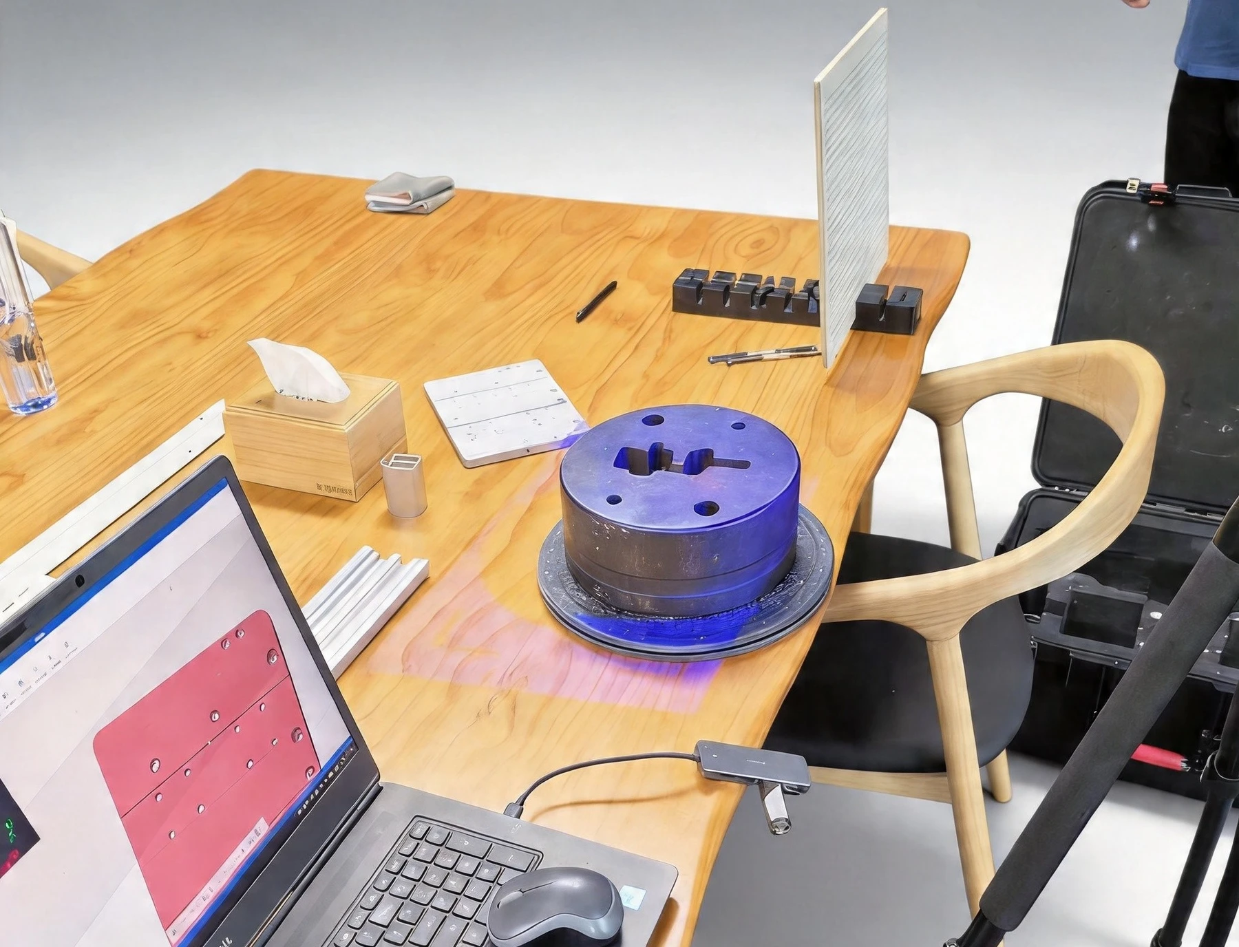
In addition, blue-light 3D scanners operate reliably in complex environments, allowing for direct use on the production floor. During the machining of mold electrodes, products can be scanned and inspected at intermediate stages of production to control accuracy throughout the process, thereby avoiding errors associated with repeated workpiece adjustments and repositioning.
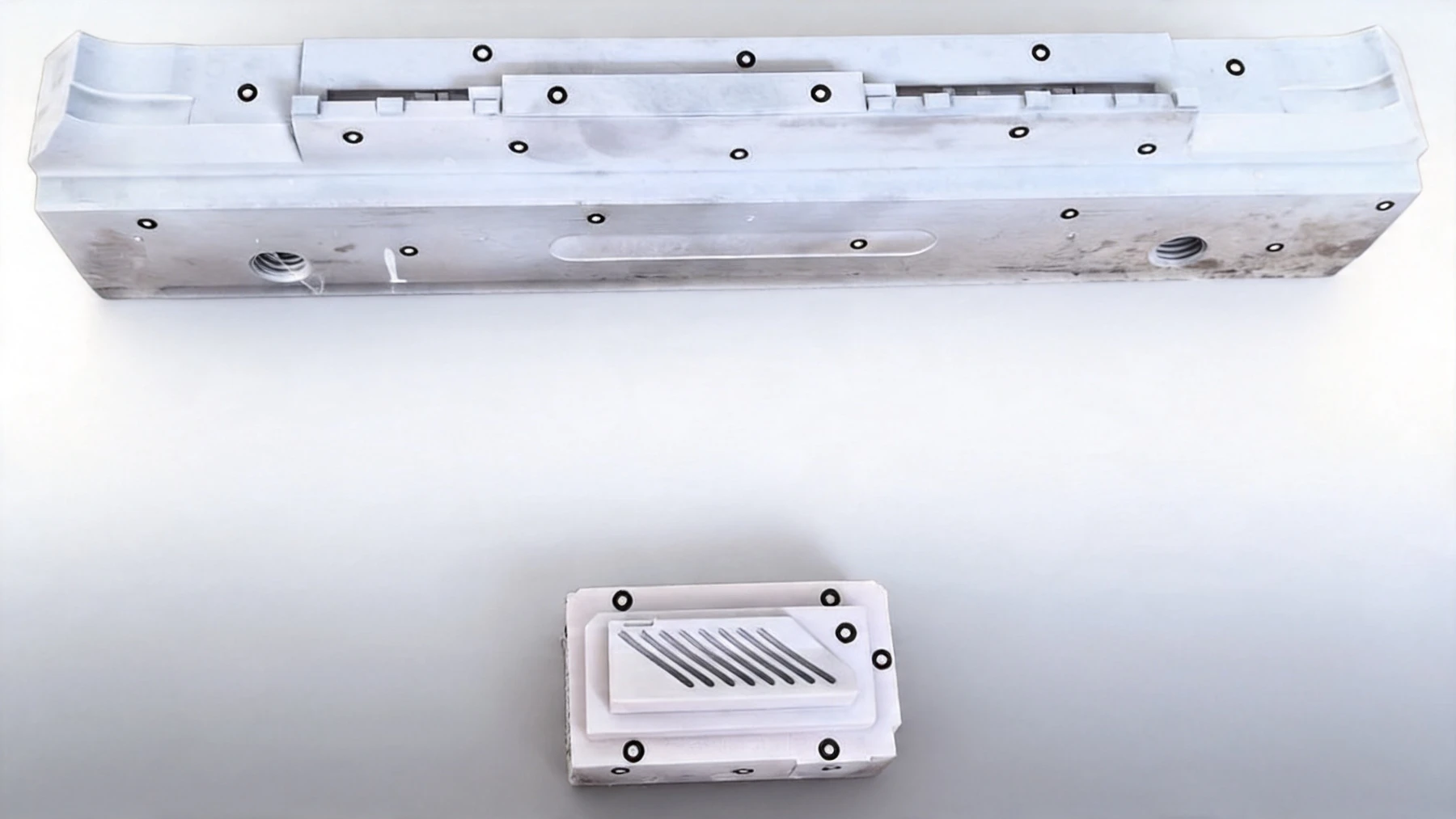
Application Value of Blue-Light 3D Scanning Technology
Electrode and Mold Quality Inspection
Electrodes feature complex structures and require high precision (tolerances ≤ ±0.02mm), making them difficult to measure using traditional methods. Blue-light 3D scanning technology enables full-dimensional inspection and comprehensive analysis of geometric dimensions and tolerances (GD&T).
Direct Verification of Spark Gaps
Traditional methods cannot directly verify spark gaps, requiring indirect calculation based on electrode dimensions. Full-dimensional 3D scanning and CAD comparison allow for the direct calculation of actual spark gap distribution across various regions, providing precise data to optimize EDM processing parameters.
Multi-Electrode Correlation Analysis
Inspection results for multiple electrodes within a single mold set are managed centrally. This allows for the analysis of dimensional and positional consistency across electrodes, the evaluation of overall assembly precision, and the identification of systemic issues that would go undetected during single-electrode inspections.
Closed-Loop Application of Inspection Data
Inspection results are fed directly back into electrode manufacturing and EDM processes:
Electrode deviation data guides EDM parameter adjustments.
Systemic deviation data guides the optimization of electrode manufacturing processes.
Historical data establishes quality records for electrodes, supporting trend analysis.
1. Quality Inspection of Cavity Electrodes and Molds
Profile/Contour Inspection:
Core Application: Precise comparative analysis between the complete 3D model of the electrode (obtained via full-dimensional scanning) and the original design CAD model.
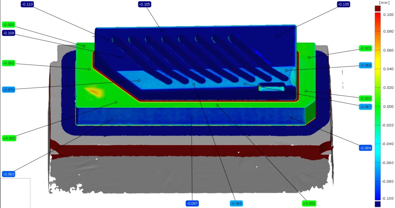
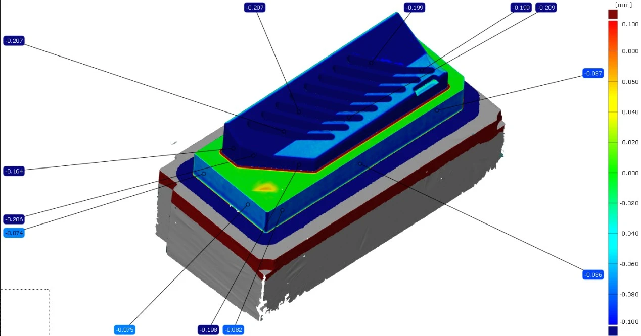
Color Map Analysis: Generation of intuitive deviation color maps that clearly display the magnitude and distribution of deviations (over-cutting or under-cutting) at various points on the electrode surface relative to the theoretical model.
Critical Area Analysis: Focused inspection of machining precision in spark-discharge zones (particularly complex surfaces, sharp corners, and fillet radii).
Critical Dimension Analysis:
Geometric Dimensions: Measurement of key dimensions such as cavity depth, width, angles, fillet radii, and draft angles.
Positional Accuracy: Measurement of relative positions, spacing, and concentricity between cavity features.
Cross-Section Analysis: Generation of cross-section lines at arbitrary locations for comparison with CAD cross-sections to verify local shape accuracy.
Electrode Wear Inspection (Secondary Inspection):
Comparison of electrode scan models from before and after use to quantify material loss caused by EDM (length compensation, profile changes), providing precise data for subsequent machining compensation or electrode replacement.
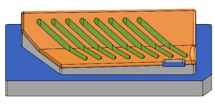
Original CAD digital model
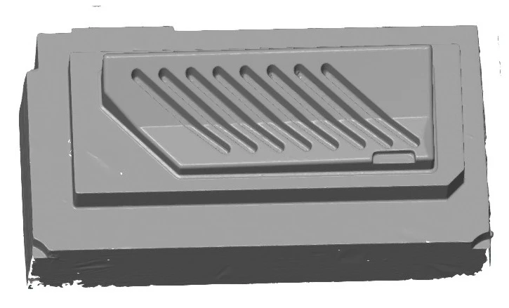
3D scan data model
2. Quality Inspection of Precision Grid Electrodes
3D Measurement of Grid Geometry:
-
Grid line width/thickness: Precisely measure the width (line width) and thickness (height) of each grid line.
-
Grid pitch: Measure the distance between the centerlines of adjacent grid lines and check for uniformity and consistency.
-
Opening size/aperture: Measure the dimensions of the gaps between grid lines.
-
Taper/sidewall angle: Measure the angle or taper variation of the grid sidewalls.
Shape Accuracy and Profile Inspection:
-
Verify that the cross-sectional shape of the grid lines meets design specifications (e.g., rectangular, trapezoidal, or arc-shaped).
-
Inspect the flatness and straightness of the grid tops and sidewalls.
-
Check for deformations such as bending, twisting, or waviness.
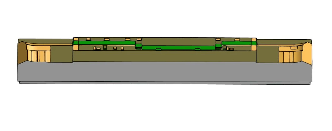
Original CAD digital model
3D scan data model
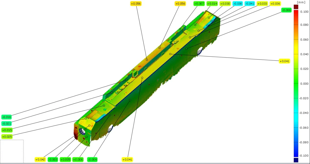
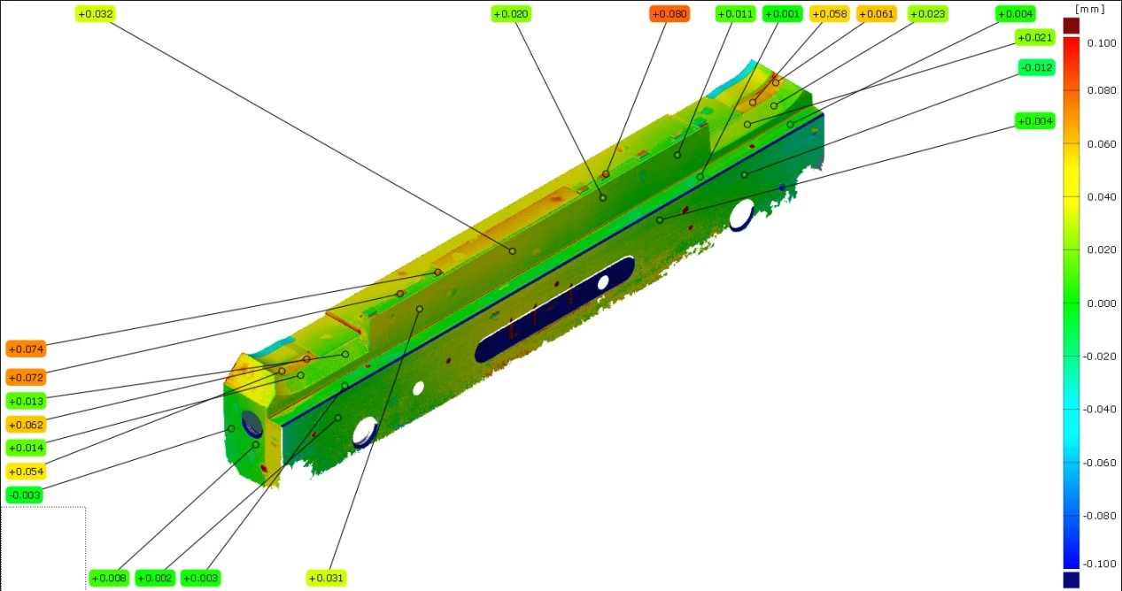
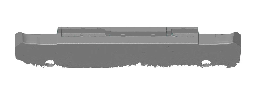
Traditional contact measurement methods can only inspect discrete points of critical dimensions, resulting in less than 10% coverage. In contrast, XTOP3D XTOM blue-light 3D scanning achieves 100% coverage, enabling the detection of localized deviations and deformations—such as localized deviation patterns and deformation trends on complex surfaces—that traditional methods might overlook.
However, non-contact measurement does have certain limitations: for applications requiring ultra-high precision (micron-level tolerances), verification using high-precision equipment like a CMM is still necessary; electrodes with extremely smooth or mirror-like surfaces require anti-glare treatment; and deep, narrow slots (with an aspect ratio exceeding 10:1) may present measurement blind spots, necessitating the use of contact probes for measurement.





















