——3D Automated Inspection Project for a Supplier to a World-Renowned Luxury Automotive Brand
I. Industry Background and Inspection Challenges
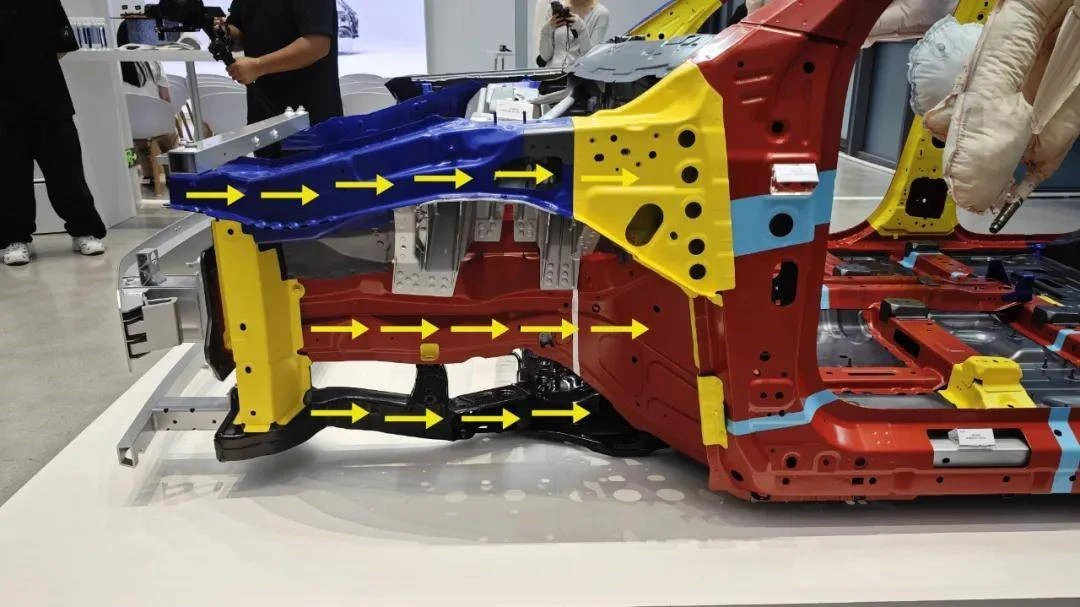
Automotive structural components feature numerous mounting points. To ensure assembly accuracy, these components require comprehensive inspection of dimensions and hole-position precision, guaranteeing that the parts entering the assembly line meet quality standards.
The front longitudinal beam weldment is a core load-bearing component of the vehicle body frame. Composed of multiple welded sheet metal stampings, its dimensional accuracy directly impacts the vehicle's safety, assembly fit, and crash performance. A prominent supplier of luxury automotive components urgently required an automated 3D inspection system—capable of high efficiency, precision, comprehensive data acquisition, and digital analysis—to more accurately monitor and control quality trends.
II. Inspection Requirements
For the automotive front longitudinal beam welded assembly in this project, addressing complex process issues—such as welding deformation and stamping springback—requires tracing data back to the molds, fixtures, or welding parameters; manual inspection lacks the necessary data support.
High-efficiency full inspection: Replacing the current spot-check model with automated full-dimensional measurement, reducing inspection time per unit to 15–30 minutes;
High-precision alignment: Tolerance accuracy of ≤±0.05mm, covering sheet metal contours, weld point coordinates, and assembly datum surfaces;
Data traceability: Generating digital comparison reports to pinpoint the source of welding deformation.
III. Inspection Difficulties and Challenges
1. High geometric complexity: The front longitudinal beam is formed by welding multiple layers of sheet metal, featuring complex geometries such as curved surfaces, bend angles, and weld hole locations;
2. Full-dimensional coverage requirement: Inspection must cover hole locations, positional accuracy, flatness, and weld seam misalignment; partial spot checks risk missing minor deformations;
3. Batch inspection efficiency bottleneck: Traditional Coordinate Measuring Machines (CMMs) rely on manual programming for positioning and are limited to spot checks or first-article inspections, failing to meet the requirement for 100% in-line inspection;
4. Difficulty in tracing welding deformation sources: Dimensional deviations caused by factors like stamping springback or fixture positioning errors require rapid tracing back to specific process stages—a task traditional methods struggle with due to a lack of data support.
Naturally, each inspection method has its own advantages. Automotive component manufacturers typically employ a combination of blue-light 3D scanning and CMMs, working in tandem to achieve inspection goals:
1. Blue-light 3D scanning focuses on efficient, comprehensive inspection: Rapidly capturing overall deformation trends and surface contour deviations;
2. CMMs precisely verify critical dimensions: Conducting absolute accuracy re-measurements on areas flagged as out-of-tolerance during blue-light 3D scanning (e.g., locating holes, assembly surfaces);
3. Cross-validation of data: Avoiding systematic errors associated with single-device systems and ensuring confidence in quality conclusions.
IV. Automated 3D Scanning and Inspection Solution
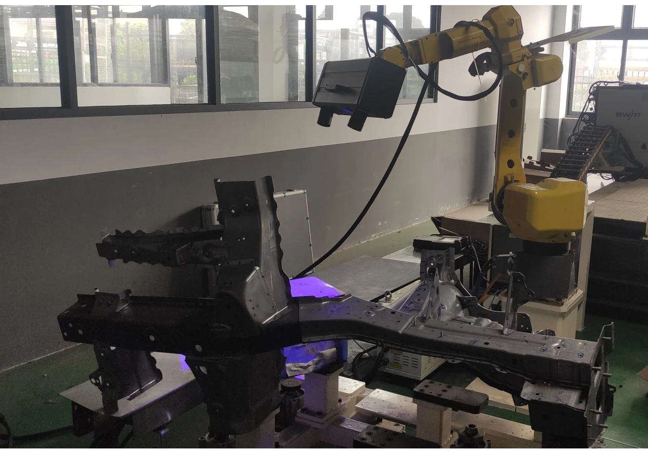
Utilizing the XTOP3D XTOM-TransForm automated 3D scanning and inspection system enables the automatic, comprehensive scanning and measurement of automotive front longitudinal beam welded assemblies and sheet metal stamped parts. This system facilitates full-scale product inspection, delivering precise, reliable, and traceable results; automated 3D inspection significantly enhances inspection efficiency and ensures effective quality control in production.
|
System Modules
|
Functional Design and Technical Specifications
|
Customer Value
|
|
6-axis robotic arm & load-bearing turntable
|
Payload of 80 kg (customizable), high repeat positioning accuracy, supports 360° full-view scanning.
|
Accommodates the large dimensions (≤500 mm) and high weight of the front longitudinal beams.
|
|
Intelligent path planning
|
Automatically generate scanning paths based on CAD models while avoiding occluded areas.
|
Automatically plan the optimal scanning path to complete the workpiece scan.
|
|
Large-format measuring head
|
The MATRIX-9M-L offers a large single-scan field of view (200×150 mm / 600×450 mm), delivering high measurement efficiency and precision.
|
Large-format scanning, suitable for the rapid acquisition of 3D data models of large-sized components.
|
|
XTOM Scanning Software
|
Single-scan accuracy of 0.015 mm, sampling point spacing of 0.15 mm.
|
Detect dimensional deviations such as springback in stamped parts, weld seam collapse, and hole positions on curved surfaces.
|
|
Template detection function
|
Create measurement templates based on automatic path planning strategies; these can be directly recalled for measuring products of the same specifications.
|
Automated measurement via one-touch scanning and inspection; the entire process requires no manual intervention.
|
|
Collision detection and emergency
|
Real-time 3D spatial simulation, emergency braking response
|
Ensure the safety of high-value workpieces and equipment.
|
V. Practical Case Study: Automated Inspection of Welded Assemblies and Sheet Metal Parts
Equipped with a large-format measuring head, the XTOM-TransForm automated 3D scanning inspection system delivers high efficiency through a wide single-scan field of view. Combined with sophisticated point cloud noise reduction and sampling algorithms, it clearly captures intricate features such as curved surfaces, hole locations, and threaded bosses.
For reflective sheet metal surfaces, the XTOM scanning software utilizes an intelligent exposure algorithm to acquire high-quality point cloud data without requiring pre-treatments like powder coating. This advantage is particularly significant in the inspection of automotive sheet metal parts, as it ensures inspection accuracy while preventing surface damage caused by powder application.
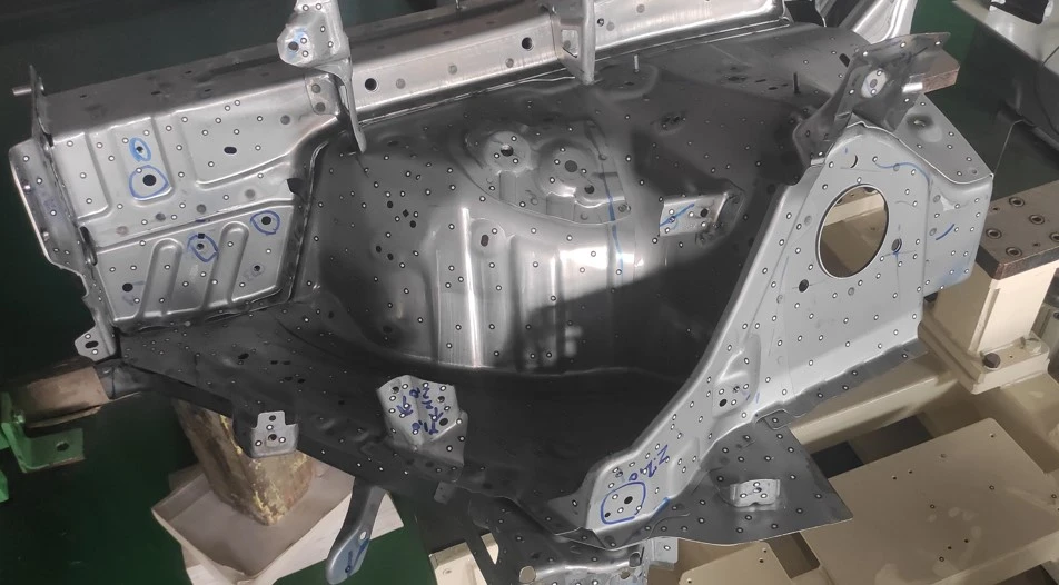
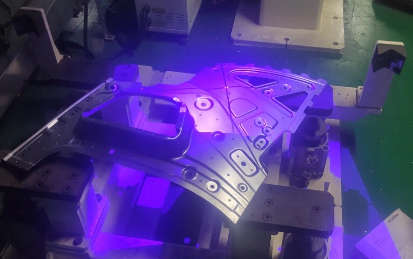
Front longitudinal member welded assembly and stamped parts
The XTOM-TransForm automated 3D scanning and inspection system, paired with inspection software, aligns scan data with the original CAD model to clearly visualize features such as hole positions, surface deviations, trim edge deviations, and geometric tolerances. By leveraging batch inspection data, the system enables real-time feedback and root-cause traceability, providing data-driven support for quality improvement and process optimization.
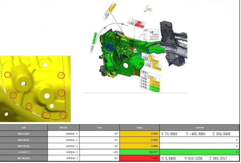
3D Full-Dimensional Inspection Report for Automotive Front Longitudinal Member Welded Assembly:
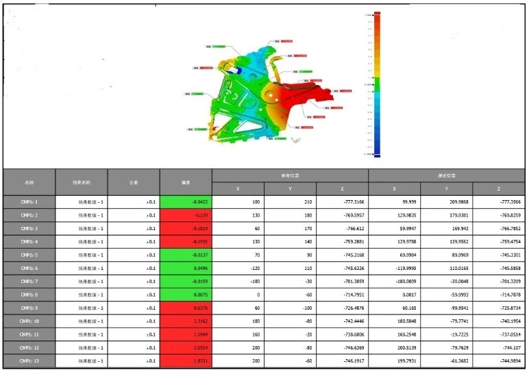
3D Full-Dimensional Inspection Report for Sheet Metal Stamped Parts:
V. Data Analysis and Results
-
Automated 3D inspection is employed, requiring 15 minutes for machined surface inspection and 15–30 minutes for full-dimensional inspection.
-
For welded assemblies, the system analyzes tolerances for stud position, tilt, and perpendicularity (0.7 mm) as well as angular dimensions (±0.5 mm), while providing tolerance compensation parameters.
-
For sheet metal stampings, key location tolerances are ±0.1 mm with deviations ranging from -0.0137 mm to 2.5924 mm; deviation data can be annotated for any specific location.
-
A high-precision grayscale edge detection algorithm enables the measurement of hole and slot positions and dimensions, ensuring no hole-position drift in individual parts and facilitating the smooth progression of subsequent manufacturing steps.





















