Automotive engine camshafts feature continuous surfaces (such as cam lobe lift profiles), complex integrated characteristics (journals, phase angles, oil holes, etc.), and stringent tolerance requirements. By utilizing blue-light 3D scanning technology—which combines non-contact full-dimensional scanning, rapid dynamic data acquisition, and intelligent global stitching—manufacturers can meet the need for high-precision, high-efficiency, full-dimensional 3D quality inspection, achieving a closed-loop inspection process that takes just 15 minutes per workpiece.
In this camshaft inspection application, blue-light 3D scanning technology enables the non-destructive acquisition of critical dimensional data—including cam lobe profile deviations, journal roundness, keyway position, and phase angle errors—to generate comprehensive GD&T reports. The results demonstrate value far exceeding that of single-point sampling; the inspection data facilitates process optimization, while the complete 3D digital inspection supports SPC process control, effectively ensuring both production efficiency and product quality.

Challenges in Traditional Camshaft Measurement
The cam lobe profile is a critical functional area of an engine; its geometry—including the profile curve, lift, phase angle, and base circle diameter—directly determines valve timing and lift, thereby impacting engine performance and emissions. Traditional inspection methods are limited to capturing discrete points, failing to provide complete, continuous surface data; they are also inefficient and prone to missing defects.
Furthermore, camshafts possess complex features, integrating multiple cam lobes (typically eight lobes for a four-cylinder engine), bearing journals, keyways, flanges, oil holes, and oil grooves. A single scan must capture all geometric information for a comprehensive assessment to facilitate rapid quality analysis, decision-making, and root-cause tracing.
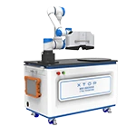
To address these challenges, an automotive camshaft manufacturer adopted the XTOP3D XTOM blue-light 3D scanner. By capturing complete and precise 3D surface data and comparing it against the original CAD model for comprehensive dimensional and geometric tolerance (GD&T) analysis, the company established a solution for precise quality control.

How Blue Light 3D Scanning Works
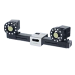
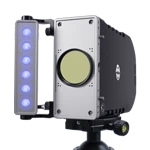
XTOM-9M photographic blue-light 3D scanner, the same device can be equipped with 2 sets of lenses, can freely switch between different measurement formats, and can take into account both local details and overall scanning efficiency.

Camshaft surface powder coating and dot application completed.
3D Scanning Data Quality Parameters:
Blue Light Source: Blue light fringe projection technology ensures stable measurement results even in workshop environments.
Measurement Accuracy: 0.008–0.01 mm (for field-of-view sizes ranging from 200×150 mm to 400×300 mm)
Sampling Point Spacing: 0.045 mm–0.09 mm (45 μm; high density for detailed capture)
Scanning Efficiency: < 1 second per scan (high-speed dynamic measurement)
Non-contact, Non-destructive Testing: Uses matte imaging spray (powder coating); causes no damage to the camshaft; suitable for finished product inspection and tooling calibration.
Camshaft 3D Scanning and Inspection Process
Workpiece Preparation: Clean the workpiece surface and apply a thin, uniform layer of high-contrast, matte developer spray (a non-destructive process) to facilitate optical 3D scanning. Evenly affix coded targets to areas such as journals and flanges.
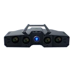
Blue-Light 3D Scanning: The XTOM-9M blue-light 3D scanner performs multi-angle scanning of the camshaft to capture comprehensive 3D point cloud data. By inspecting the surface geometry in its entirety, it completely eliminates the risk of missing quality defects.
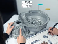
Data Processing: The XTOM 3D scanning software automatically handles point cloud generation, as well as precise point cloud alignment and merging, resulting in a complete, unambiguous 3D point cloud model with a unified coordinate system.


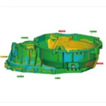
Original CAD models and 3D scanned models
GD&T and Full-Dimensional Reporting
Utilizing 3D inspection software, point cloud data is precisely aligned with the original CAD model (using methods such as best-fit or specific datum constraints, like the center bore axis). This allows for a clear visualization of full-scale geometric tolerances, enabling process engineers to rapidly adjust manufacturing processes, reduce quality assurance costs, and prevent defective parts from reaching the assembly line.
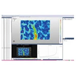
Full-scale GD&T comparison: Intuitively displays machining errors at various points along the cam profile and precisely quantifies maximum deviation values.
Automatic calculation of lift curve deviation, base circle diameter deviation, and total profile deviation.
Journal dimensions: Diameter, cylindricity, coaxiality, and straightness.
Phase angle/angularity: Relative angular relationships between cam lobes.
Dimensional and positional characteristics of features such as flanges and keyways: Length, width, depth, keyway symmetry, flange runout, etc.


Inspection Highlights and Value
100% Profile Data: Provides complete data on the camshaft's entire rotating surface and edges, eliminating the risk of missed defects associated with localized assessment.
Deviation Visualization: Color maps display spatial distribution intuitively, precisely pinpointing error zones, significantly boosting analysis efficiency and guiding process optimization.
Rapid Inspection Workflow: Reduces the inspection time for a single camshaft to just over ten minutes while enabling full-dimensional inspection.
One-Click Reporting: Allows for pre-defined report templates containing all key dimensions, tolerances, and color maps; generates professional, fully traceable inspection reports with a single click after scanning.
Supports Full-Dimensional Analysis and SPC: Provides a rich, consistent, and high-density data source for quality control departments to implement comprehensive Statistical Process Control (SPC).
Actual results demonstrate that using the XTOP3D XTOM blue-light 3D scanner for automotive camshaft inspection yields high-quality, full-surface 3D data models—even in industrial shop-floor environments. The intuitive color maps and analysis reports make it ideal for quality inspection and design verification of components featuring complex surfaces and high precision requirements.
Image-based measurement methods—characterized by non-contact operation, high speed, wide dynamic range, and rich information content—are widely used in engine manufacturing and represent a cutting-edge trend in automotive inspection technology. The XTOM blue-light 3D scanner offers a fast, convenient solution for inspecting precision-machined automotive shafts, helping manufacturers control machining quality, reduce defect rates, and ultimately lower costs associated with rework.
Upgrading quality control for your automotive parts supply chain? Contact our metrology experts to schedule a live demo or request a free sample inspection today.