Background
Due to their excellent strength, corrosion resistance, and fatigue resistance, nickel-based materials are widely used in critical components such as aero-engine blades and gas turbines. However, accurately assessing their mechanical properties during service—particularly regarding localized deformation and fracture behavior—remains challenging. Traditional strain gauges are limited to single-point measurements, while finite element simulations rely on material model assumptions, making it difficult to capture the dynamic strain distribution and fracture evolution of the material during actual tensile testing.
In this case study, Digital Image Correlation (DIC) technology is employed to monitor the full-field strain of a standard nickel-based material tensile specimen. This approach reveals the mechanical response throughout the entire process—from tensile deformation to fracture—providing a data-driven basis for material design optimization and failure prevention.
DIC Principles, Technology Comparison, and Significance
DIC Principles
The XTOP3D XTDIC 3D full-field strain measurement system utilizes image-matching algorithms to calculate full-field displacement and strain distributions by tracking the displacement of a random speckle pattern applied to the material's surface. Its core steps include:
Image Acquisition: Creating a high-contrast speckle pattern on the specimen surface and using high-speed cameras to continuously capture images of deformation during the loading process.
Correlation Calculation: Calculating displacement vectors for image subsets before and after deformation using grayscale matching algorithms (such as Zero-Normalized Cross-Correlation, or ZNCC).
Strain Field Reconstruction: Deriving full-field strain (e.g., Green-Lagrange strain, engineering strain) from the displacement gradient tensor.
DIC supports both 2D (2D-DIC) and 3D (3D-DIC) measurements; this case study employs 3D-DIC to eliminate errors caused by out-of-plane displacement.
Technical Comparison: DIC vs. Traditional Methods
Indicators
|
DIC technology
|
Conventional strain gauge
|
Finite Element Analysis (FEA)
|
Measurement dimensions
|
Full-field 2D/3D strain
|
Single-point strain
|
Full-field simulation, relying on model assumptions.
|
Data authenticity
|
Based on actual deformation; no contact interference.
|
Contact-based; susceptible to the quality of the component placement.
|
Numerical approximation; experimental verification required.
|
Motion capture capability
|
Supports high-frequency sampling (1 Hz in this case).
|
Limited response speed (<10 Hz)
|
Primarily static or quasi-static analysis
|
Fracture capture accuracy
|
Capable of locating crack initiation and propagation paths.
|
It can only indicate the overall break point.
|
Failure criteria must be preset; the error is significant.
|
Importance of DIC Technology Applications
Monitoring of localized strain concentration: Captures strain localization behavior in nickel-based materials, preventing failure from being masked by averaged values.
Investigation of failure mechanisms: Reveals the correlation between strain localization and crack propagation paths in nickel-based materials.
Process optimization: Validates the impact of material anisotropy on tensile properties, guiding material selection and improvements to processing techniques.
Quality control: Provides high-precision experimental data for simulation models (e.g., ABAQUS), enhancing prediction reliability.
System Components and Key Specifications
DIC Measurement System Components (Hardware & Software)
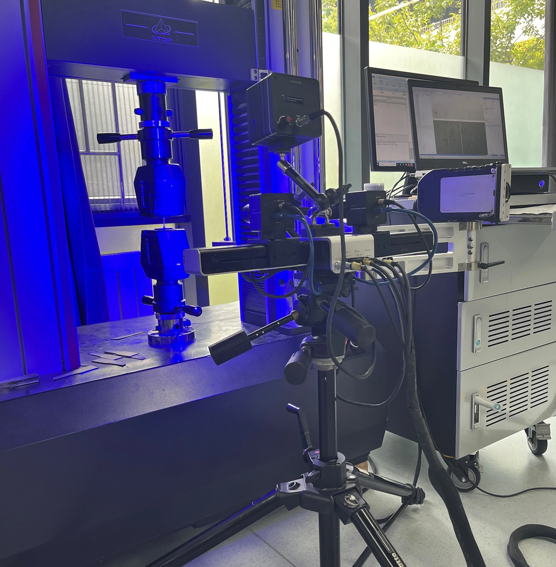
Imaging System: Binocular industrial DIC cameras and a synchronous trigger controller.
Illumination System: Blue LED cold light source (to eliminate ambient light interference) providing uniform illumination of the specimen surface.
Speckle Patterning: Matte black base coat with matte white speckle application.
Image Processing: DIC software supporting sub-pixel interpolation algorithms.
Data Analysis: Full-field strain mapping, principal strain orientation, and quantitative analysis of crack opening displacement (COD).
Problems Addressed
Quantification of strain gradients in localized necking regions of nickel-based materials.
Dynamic tracking of crack initiation sites and propagation rates.
Characterization of strain distribution non-uniformity caused by material anisotropy.
Practical Case: Tensile Testing of Nickel-Based Materials
(1) Preliminary Static Analysis
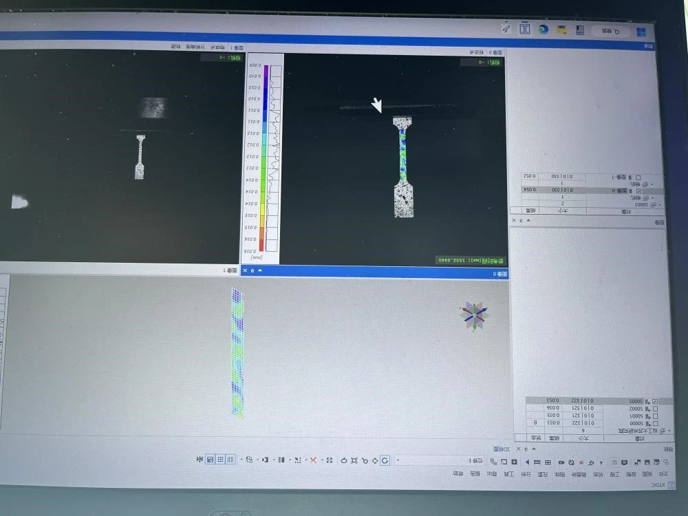
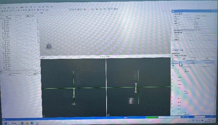
Before the experiment, the XTDIC 3D full-field strain measurement system was used to capture data and perform a preliminary analysis of the specimen in its static state. Once it was confirmed that the strain map data could be fully calculated, the formal tensile strain measurement experiment was conducted.
(2) Commencement of the formal experiment
The XTDIC 3D full-field strain measurement system begins image acquisition, the testing machine initiates the tensile test according to preset parameters, and the DIC binocular cameras fully record the tensile process.
Case Study: Data and Analysis
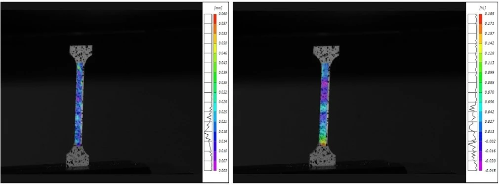
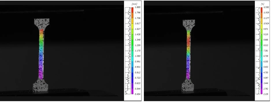
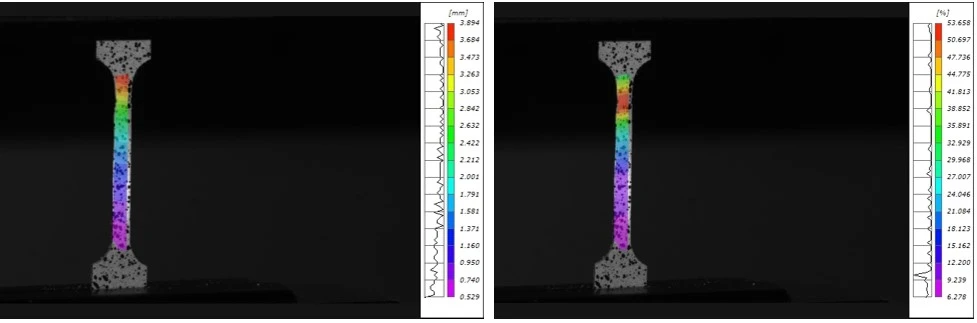
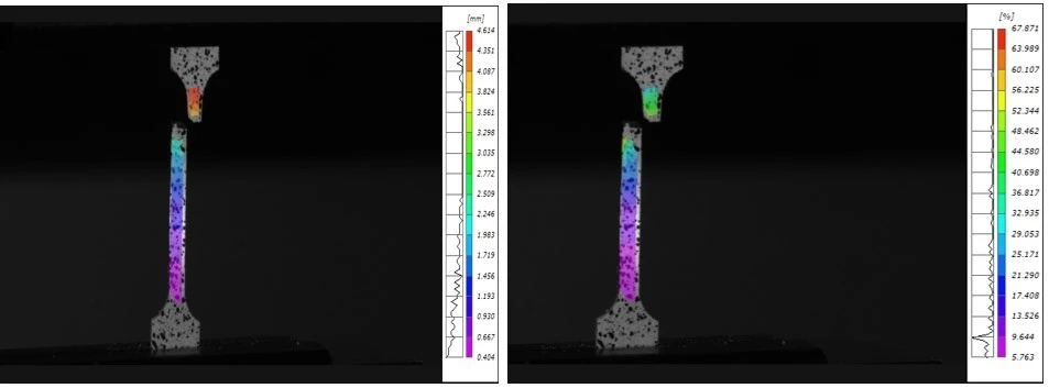
During the tensile testing of the specimen, the DIC software generates displacement and strain maps for various stages.
Initial tensile state:
Displacement & Strain Contour Plots
During Tensile Loading:
Displacement and Strain Contour Maps
Before Fracture:
After fracture:
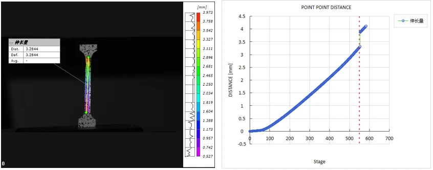
Select the distance between points and export the curve showing the variation of displacement/elongation over time from the DIC software.
Data Analysis
1. Full-field deformation analysis: Generates displacement maps (to identify deformation uniformity and zones of localized deformation, such as the onset of necking) and strain maps (to analyze strain localization and anisotropy, and to validate the accuracy of material constitutive models).
2. Fracture mechanism and failure prediction: Analyzes strain concentration zones at the moment of fracture; reveals crack initiation sites and propagation paths; quantifies true strain in the necking region; and addresses the limitations of traditional engineering stress-strain curves.
3. Displacement/Elongation vs. Time curves: Correlates data with loading conditions (e.g., strain rate) to analyze dynamic response characteristics across the elastic stage, yield plateau, plastic flow, and necking stage, thereby revealing the strain-rate sensitivity of nickel-based materials.
4. Simulation validation and design optimization: Full-field strain data obtained via DIC can be used to validate the accuracy of numerical simulations (e.g., ABAQUS) and to optimize material parameters (such as hardening models and damage parameters).