Experimental Background
In the field of 3D printing, resin materials offer exceptional printing precision and are well-suited for producing complex geometric structures and intricate components, opening up new possibilities for the efficient manufacturing of complex structural parts, functional prototypes, and end-use products.
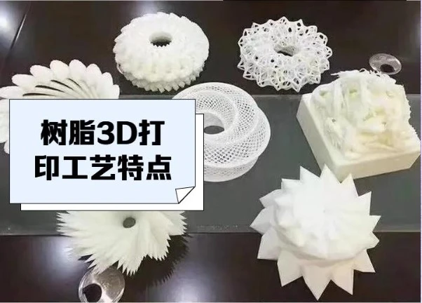
For complex 3D structures created via 3D printing, analyzing mechanical behavior under compressive loads—including deformation processes, full-field strain evolution, and strain concentration zones—is crucial for manufacturing products with complex mechanical requirements and ensuring the reliability of their mechanical performance.
DIC Principles and Technology
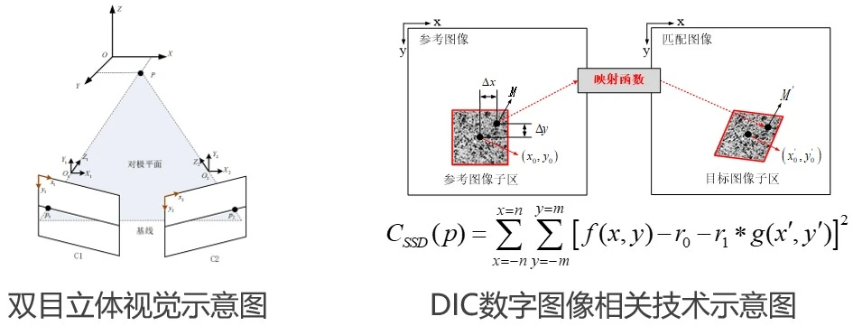
The XTOP3D XTDIC 3D full-field strain measurement system integrates Digital Image Correlation (DIC) with binocular stereo vision technology. By tracking speckle patterns or distinctive features on an object's surface and performing stereo matching and 3D reconstruction, the system enables dynamic measurement of full-field 3D coordinates, displacements, and strains during deformation. It features non-contact operation, portability, high speed, high precision, ease of use, and real-time measurement capabilities. It is particularly well-suited for measuring deformations in high-frequency dynamic, non-linear, or complex structures.
Comparison of Strain Measurement Techniques
Traditional measurement methods typically rely on contact-based sensors, such as strain gauges and accelerometers. These sensors primarily measure localized stress and strain, making it difficult to obtain full-field deformation data for the structure.
Contact-based measurement methods require physical contact with the specimen; this can affect the specimen's self-weight, thereby influencing testing accuracy and data results.
Traditional methods often require specific surface treatments or geometric constraints, limiting their suitability for measuring complex geometries and making it difficult to capture detailed deformation data.
DIC Technology for Full-Field Deformation Measurement
DIC technology captures contour data in a reference state and tracks the displacement of corresponding points under various mechanical loads, enabling the calculation and analysis of strain data.
Supported by multidimensional data, the analysis of compressive deformation in 3D-printed resin structures becomes straightforward and reliable. DIC technology allows for the visualization of full-field strain evolution and distribution on the structure's surface during compression, as well as strain concentration in critical load-bearing areas, providing researchers with a comprehensive map of stress and strain distribution.
Key Indicators of XTOP3D DIC Technology
-
Non-contact measurement technology;
-
Full-field measurement of XYZ 3D coordinates, displacement, and strain;
-
Measurement range up to 500 mm;\Strain measurement accuracy up to 20 με;
-
FEA comparison;
-
Real-time full-field strain calculation and result display (no post-processing required).
Experimental Procedure
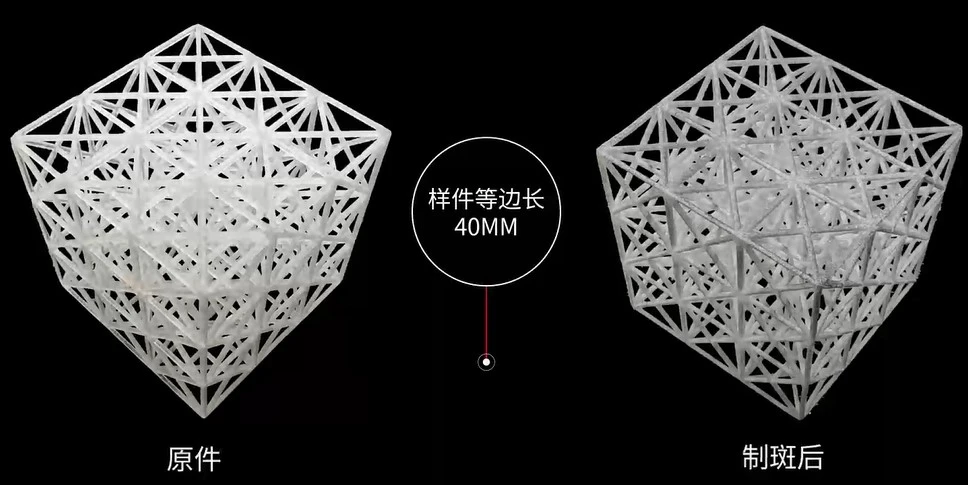
Speckle Pattern Preparation: Create a speckle pattern on the specimen surface, ensuring the pattern's uniformity and contrast so that the DIC system can accurately identify and track it.
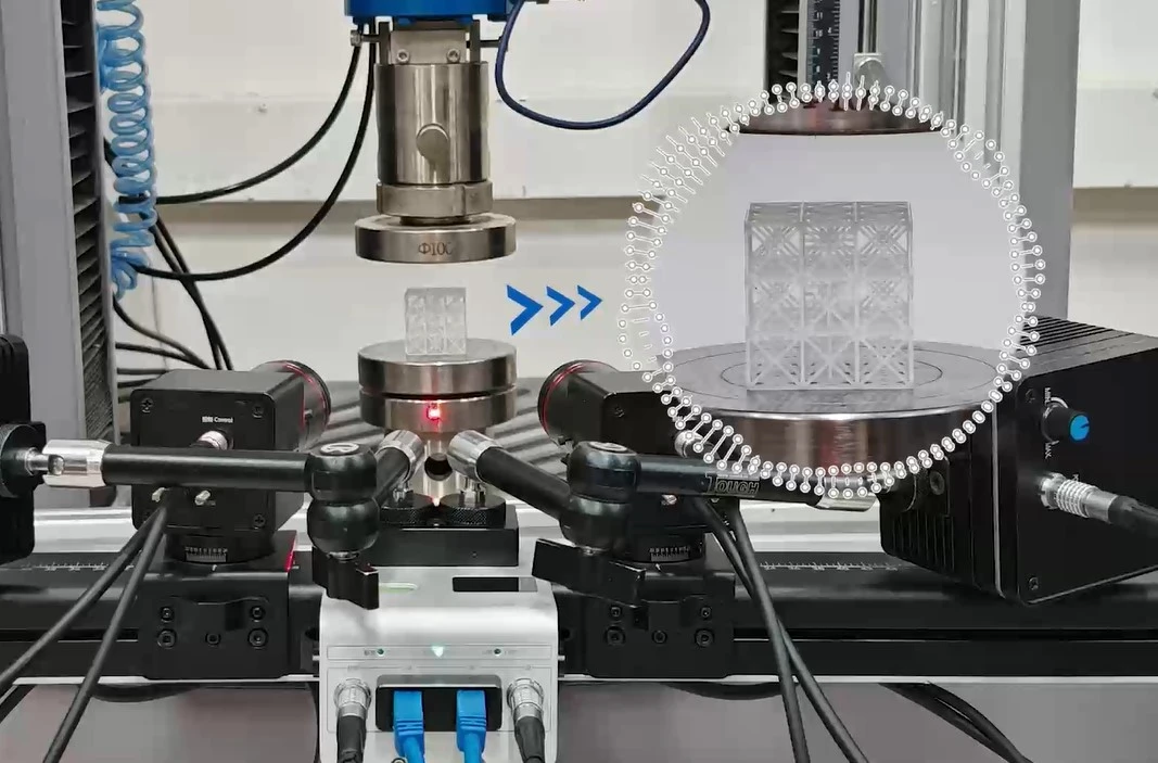
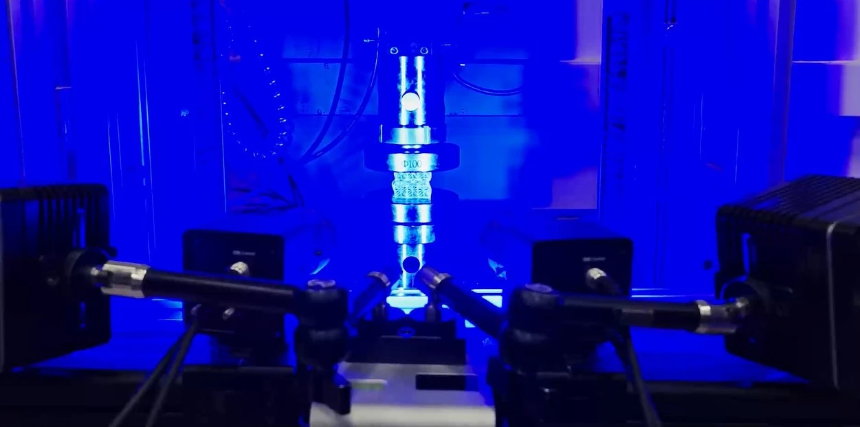
DIC Installation and Calibration: Install the camera and illumination source, ensuring the camera can clearly capture the speckle pattern on the specimen surface. Perform DIC system calibration to ensure the accuracy of the camera's intrinsic and extrinsic parameters, thereby enhancing measurement precision.
Image Acquisition: The testing machine initiates the compressive loading process, while the DIC system simultaneously captures images of the specimen undergoing deformation. Ensure that the image acquisition frequency and resolution meet the experimental requirements. Concurrently, the DIC system software monitors the specimen's displacement and strain distribution in real time.
Data and Analysis
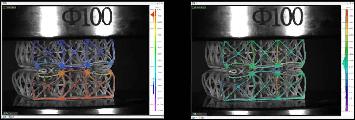
Measurement Data: The Y-direction and Z-direction displacement contour maps for a specimen with a complex structure (made of 3D-printed resin) at a critical deformation stage during compression testing are shown below:
Y-direction displacement contour plot Z-direction displacement contour plot
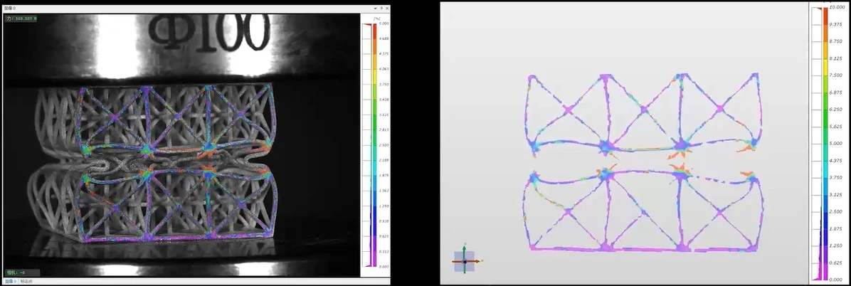
Measurement data: The maximum principal strain contour map and 3D maximum principal strain contour map of a complex-structured 3D-printed resin specimen—captured during a critical deformation stage of compression testing—are shown below.
Maximum principal strain contour plot; 3D contour plot of maximum principal strain.
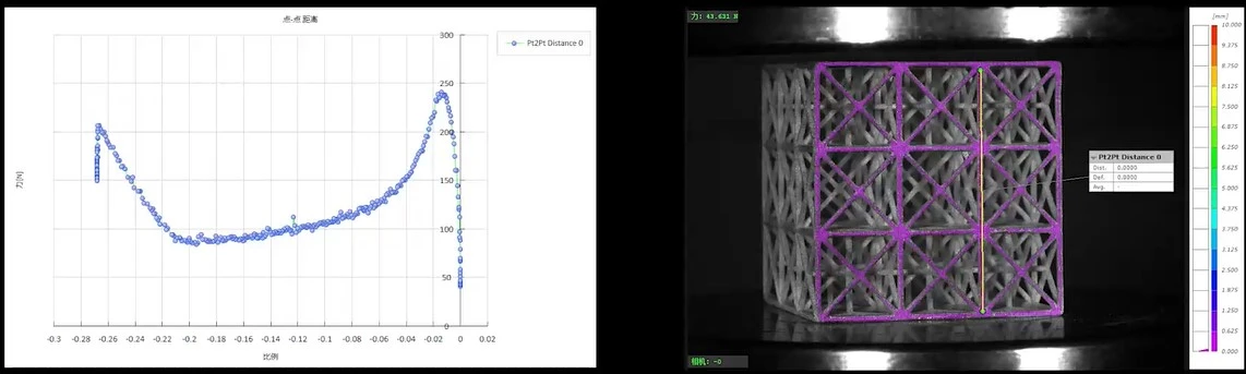
Measurement data: During the compression testing of a complex-structured specimen made of 3D-printed resin, the strain-force curve (derived from the communication between the DIC system and the testing machine) and a schematic of the linear strain on the structure's surface are presented below:
Strain-force curve; schematic diagram of linear strain.
Data Analysis Conclusions
The XTDIC 3D full-field strain measurement system was used to calculate and analyze the displacement and strain fields on the surface of the 3D-printed resin structure. Displacement vectors for individual points were determined by matching speckle patterns between the initial and deformed images using correlation algorithms.
The DIC software generated full-field strain maps, providing a visual representation of the strain distribution across the specimen during compression. These maps allowed for the clear observation of dynamic displacement changes in the Y and Z directions and facilitated the analysis of regions experiencing maximum principal strain.
The experimental results are presented in the form of charts, curves, and strain maps, facilitating analysis and discussion by researchers and engineers.