Cracking is a critical parameter characterizing the state of concrete structures under load. Due to the complex composition and mechanical behavior of concrete, conducting detailed studies on its deformation characteristics, strain distribution, and crack propagation presents significant challenges. Traditional strain gauges and displacement sensors are limited by spatial constraints regarding their placement and quantity. Furthermore, methods such as ultrasonic testing, acoustic emission, radiographic inspection, and fiber Bragg grating struggle to provide quantitative analysis of cracks. Consequently, there is an urgent need for a new approach to investigate the deformation and cracking characteristics of concrete structures.
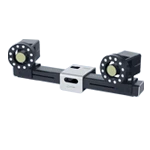
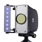
The XTOP3D XTDIC 3D full-field strain measurement system enables fully automated, high-precision, non-contact measurement of cracks across the entire field of view. By tracking displacements in speckle patterns and smoothing the data, the system employs correlation algorithms to calculate specimen strain. Additionally, it utilizes digital image processing techniques to detect crack characteristics—such as size, length, and orientation—thereby providing a comprehensive, reliable, and precise method for crack measurement in concrete loading experiments.

DIC Technology Applications and Innovations
1. Crack Detection Based on Principal Strain Fields
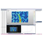
Crack propagation tests are conducted using the XTDIC 3D full-field strain measurement system to locate cracks based on principal strain fields. When concrete cracking causes a gradient in the displacement field, the principal strain increases at the location of the crack. By analyzing features within the principal strain field resulting from cracking, the DIC software enables full-field crack localization.
2. Large-Field-of-View Full-Field Strain Measurement
The XTDIC 3D full-field strain measurement system supports a calibration method that decouples internal and external parameters, thereby overcoming calibration challenges associated with large fields of view for concrete beam structures. To align all images within a single, unified coordinate system for reconstruction, the local coordinate system of a specific camera can be designated as the primary reference.
3. Multi-Camera 3D Digital Image Correlation
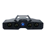
For deformation measurements of large-scale concrete beams, a camera network comprising multiple cameras is employed to ensure high resolution and accuracy across the large-scale, full-field deformation measurement.

Unified Extrinsic Calibration for Multi-Camera Systems Based on Coded Points
Loading Test on Concrete Beams
1. Specimens and Loading
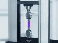
Standard rectangular reinforced concrete beams with bottom reinforcement were used. They were mounted on a universal testing machine for three-point bending tests, employing displacement control to simulate quasi-static loading.
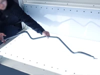
Specimen Preparation: A high-contrast, fine, random black-and-white speckle pattern was sprayed onto the observation surface (side face) of the concrete beam to serve as textural features for DIC tracking.

Creation of speckle patterns on concrete beams
2. Data Acquisition
During the loading process of the testing machine, the XTDIC 3D full-field strain measurement system and the loading control system are triggered synchronously to capture image sequences from the left and right cameras simultaneously at preset load levels.
DIC Technology Application and Analysis:
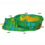
1. Acquisition of Full-Field Displacement and Strain Fields
DIC software processes the captured image sequences; by matching left and right views and tracking the movement of speckle patterns, it calculates the full-field 3D displacement and strain fields on the specimen surface.
Result Visualization: Color contour maps are generated for various loading stages (e.g., near and beyond cracking, yielding, and ultimate loads), intuitively displaying the surface displacement distribution and regions of strain concentration (particularly regarding principal strain and maximum tensile strain).
2. Displacement and Strain Curves at Key Points
Virtual points or paths are defined within the DIC software at critical locations, such as the bottom of the beam at mid-span (point of maximum bending moment), along expected crack paths (e.g., flexure-shear zones), and above reinforcement locations.
Data Extraction: 3D displacement data (e.g., mid-span deflection) and strain data (e.g., maximum tensile strain at the beam bottom) for these key points are extracted across all loading steps.
Curve Plotting:
Load-Displacement Curve: Plots the load recorded by the testing machine against the mid-span deflection measured by the DIC system.
Load-Strain Curve: Plots the load against the strain at key points (e.g., the center point at the beam bottom).
These curves clearly illustrate:
Identification of Cracking Point: The load-strain curve exhibits a distinct inflection point or abrupt change (strain release) when the concrete's tensile strength is reached; this indicates initial crack formation more sensitively than the load-displacement curve.
Crack Propagation Stages: Changes in curve slope reflect stiffness degradation, corresponding to stages of stable and rapid crack propagation.
1. Analysis of displacement at the crossbeam loading point:

Displacement/Strain Field Calculation
Extract the locations of corresponding points on the left and right sides of the beam using the DIC software, and plot the displacement and strain curves for these points:

Displacement curve of Point 2 & Displacement curve of Point 3
2. Analysis of displacement at the mid-span of the crossbeam:

Displacement/Strain Field Calculation
Extract the key point at the mid-span of the beam using the DIC software and plot the displacement-time curve for that point:

Displacement curve for Point 0 & Displacement curve for Point 1
3. Crack Width Measurement and Propagation Analysis
Principle: The full-field 3D displacement field calculated via DIC serves as the basis for measuring crack width.
Method:
1. Crack Identification: Identify and define the crack path within the DIC software based on maximum principal strain maps or regions of displacement discontinuity.
2. Point-Pair Definition: Define one or more sets of virtual point pairs on either side of the identified crack (oriented perpendicular to the crack direction). The initial spacing of these point pairs is determined in the uncracked state or from the reference image.
3. Width Calculation: The DIC software automatically calculates the width values for multiple point pairs along the crack path.
4. Width Evolution Curves: Plot curves showing the variation of crack width—either at a specific location (such as the widest point of a mid-span crack) or as an average along the crack length—against load or time (deflection). Width curves for cracks at different locations can be plotted for comparative analysis.

Calculation of crack solutions under beam loading
In the DIC software, select key points at the crack locations on the left and right sides of the beam and export the data for these points; this allows for the plotting of a curve representing the absolute value of the distance between them.

Dot Pitch Curve for Point 6 & Dot Pitch Curve for Point 13
Application Value of DIC Technology
1. Non-contact, full-field, and continuous: It eliminates the need to touch crack edges, enabling continuous and automated measurement of crack widths at any point along the crack path during the loading process.
2. High precision and resolution: Precision reaches the sub-pixel level (typically better than 0.01 mm), with resolution determined by speckle size and camera resolution.
3. Quantification of the propagation process: It accurately records the entire process of crack evolution—from initial micro-opening to macroscopic propagation—and captures the relationship between crack width and increasing load (e.g., linear growth, non-linear acceleration).
4. Assessment of reinforcement and material effects: By comparing beams with varying reinforcement ratios, concrete strengths, or admixtures, DIC data allows for the quantitative analysis of how these factors influence crack spacing, width, and propagation patterns, thereby providing a basis for design optimization and material selection.
The XTOP3D XTDIC 3D full-field strain measurement system enables non-destructive, continuous monitoring of concrete structures throughout the loading process. It accurately identifies the onset and location of initial cracking, visually maps the evolution of full-field displacement and strain, and reveals the mechanisms of crack initiation and propagation. Furthermore, it automatically and quantitatively measures crack widths and their development along the crack path. By providing rich, precise experimental data, the system facilitates a deeper understanding of failure mechanisms in concrete structures, supports the validation and refinement of theoretical models, guides engineering design and assessment, and offers critical data to enhance structural safety and durability.