In the fields of microelectronics, advanced materials, and precision manufacturing, as the characteristic dimensions of components and materials shrink to the micron or even sub-micron scale, traditional Digital Image Correlation (DIC) measurement methods struggle to meet the demands of micro-scale measurement.
Micro-Digital Image Correlation (Micro-DIC) technology, combined with high-temperature experimental setups using thermal control chambers (or heating/cooling stages), has emerged as a key method for investigating the micro-scale thermo-mechanical behavior of materials, thanks to its advantages of being non-contact, full-field, and high-resolution. Taking the XTOP3D XTDIC-MICRO system as an example, this article provides a detailed analysis of the principles, procedures, key technical challenges, and typical applications of this experimental technique.
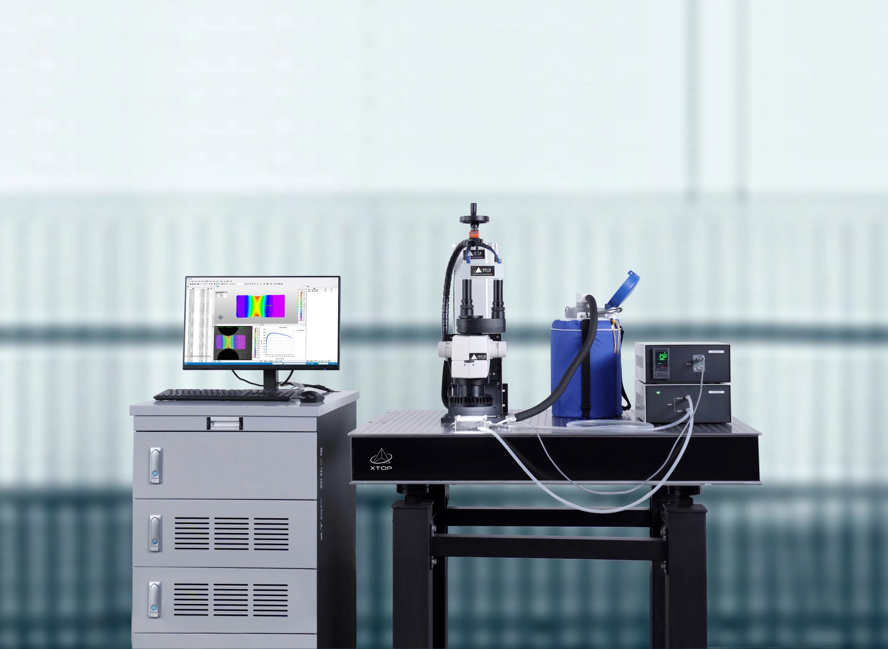
I. Technical Principles and System Composition
Microscopic DIC (Digital Image Correlation) technology is essentially a measurement method that combines digital image correlation algorithms with a high-magnification optical microscope system. Its basic principle is to prepare random speckle patterns on the surface of the microscopic sample to be measured, record the image sequence of the sample before and after thermal deformation using a high-resolution camera, and use correlation algorithms to track the displacement of the speckle field, thereby calculating the strain, displacement, and three-dimensional morphological changes in the entire field.
When used with a temperature control chamber (usually an optical hot and cold stage), the system mainly consists of the following core units:
Microscopic DIC measurement head : such as the XTOP XTDIC-MICRO microstrain measurement system, which integrates a high-magnification microscope, dual industrial cameras (supporting 2D/3D measurement), a high-precision light source, and dedicated DIC analysis software. Its measurement field of view is typically between 1mm and 10mm, and the strain measurement accuracy can reach up to 20με (microstrain), which can clearly capture microscopic details.
Temperature-controlled loading unit : also known as a temperature control chamber or optical hot and cold stage, responsible for providing a precise and controllable temperature environment. Taking the solution adapted to the XTOP micro DIC measurement system as an example, the temperature range can reach -190℃~600℃ (customizable), equipped with a heat insulation cover, observation window and high-precision temperature control module (temperature control accuracy can reach ±0.1℃).
Vibration isolation and auxiliary platform : Since microscopic measurements are extremely sensitive to vibration, the system usually needs to be equipped with a pneumatic vibration isolation platform and an automatic calibration turntable to ensure the stability of the measurement reference.
II. Detailed Operating Procedures for High Temperature Experiments
Based on the practical application specifications of the XTOP XTDIC-MICRO microstrain system, a standard high-temperature microscopic DIC experiment typically includes the following steps:
1. Sample preparation and speckle pattern fabrication
This is the foundation for experimental success. Tiny-sized samples (such as single-crystal silicon wafers, chip packages, micro-samples, etc.) need to be cut or prepared according to the microscope's field of view. Subsequently, a high-contrast, high-temperature-resistant speckle pattern is fabricated on the test area of the sample. For high-temperature experiments, the speckle must be able to withstand thermal expansion, oxidation, or ablation. XTOP solutions typically provide tiny speckle preparation tools or parametric speckle preparation techniques to ensure that the speckle remains clearly discernible under temperature changes.
2. System Setup and Calibration
The sample was fixed on the stage of the temperature-controlled chamber, and the microscope magnification was adjusted and focused. System calibration was then performed: using a fully automatic calibration turntable and calibration plate, the camera's internal and external parameters and lens distortion were calibrated with a single click. The XTOP XTDIC-MICRO system features a unique image distortion correction algorithm that effectively eliminates the interference of non-parametric deformation and optical distortion of the stereo microscope on microscopic strain calculations.
3. Temperature program setting and preliminary experiment
Set the temperature profile in the temperature control chamber software (e.g., heating from 25℃ to 300℃ at a rate of 10℃/min, and holding at the target temperature for a certain period). It is recommended to perform a heating and cooling cycle before formal data collection to eliminate internal stress in the sample and ensure stable heat conduction.
4. Synchronous data acquisition
Simultaneously with temperature control, activate the microscopic DIC system to synchronously acquire images at a set frequency (e.g., one image every 6 seconds or 1 Hz). Note that after reaching the target temperature, it is usually necessary to maintain the temperature for a period of time (e.g., 2-5 minutes) until the overall temperature of the sample is uniform, thermal expansion is stable, and the microscopic field of view is clearly focused before recording images, in order to avoid data noise caused by thermal inertia or airflow disturbances.
5. Data Processing and Result Analysis
After the experiment, the images were imported into the DIC analysis software. By selecting the speckle area and adding seed points, the software could calculate the full-field displacement contour map, strain distribution, warpage, and coefficient of thermal expansion (CTE) at each temperature node. XTOP DIC software supports 3D model reconstruction and can output in-depth data such as cross-sectional thermal deformation effects and deformation gradients of different layers.
III. Core Challenges and Solutions in High-Temperature Microscopic DIC Experiments
Performing high-temperature DIC measurements at the micrometer scale presents several unique challenges, which are also key to evaluating the professionalism of a system (such as XTOP XTDIC-MICRO):
Thermal radiation and image interference : At high temperatures, the sample emits red/infrared thermal radiation, causing image overexposure or decreased speckle contrast. Solutions include using blue/ultraviolet LEDs for supplemental lighting and installing a narrow-band filter in front of the lens to filter out the thermal radiation band, receiving only specific wavelengths of illumination to ensure image quality.
Thermal turbulence (thermal fog) : The convection of hot air outside the observation window of the temperature control box can deflect the light path, causing image drift or distortion. Usually, an air knife (blowing inert gas) or a horizontal fan is introduced between the lens and the viewing window to drive the cooling airflow and ensure the stability of the light path.
Out-of-plane displacement and defocusing : The depth of field in a microscopic field of view is extremely shallow, and out-of-plane displacement (Z-axis) due to the thermal expansion of materials can easily cause the image to go out of focus. XTOP XTDIC-MICRO, through algorithm optimization and specific microscopic configuration, can effectively control the impact of out-of-plane displacement on in-plane strain calculation, and can be combined with an autofocus module when necessary.
Spot stability : Ordinary spray paint spots may crack and peel off at high temperatures. High-temperature resistant coatings or special surface pretreatments (such as micro-etching or precious metal sputtering) are required to ensure that the spot characteristics are continuously traceable throughout the entire temperature range.
IV. Typical Application Scenarios
Semiconductor chip thermal warpage testing : This test measures the three-dimensional warpage deformation of BGA or CPU chips under the reflow soldering temperature profile and analyzes the stress concentration caused by CTE mismatch between different material layers (silicon wafer, substrate, molding compound). It is an essential test for improving chip reliability.
Micromaterial CTE Measurement : Precise measurement of the coefficient of thermal expansion of materials such as single-crystal silicon, fine metal wires, and thin films. Microscopic DIC records the change in length over a micrometer scale with temperature, calculates strain per unit temperature, and the data can be directly used for finite element analysis (FEA) model verification.
In-situ thermo-mechanical coupling test of micro-samples : Combined with a micro-force testing machine, observe the in-situ tensile/compression deformation and crack initiation behavior of microelectromechanical systems (MEMS) devices or micro-metal samples under high temperature environment.
Conclusion
Microscopic DIC measurement technology, combined with a temperature-controlled chamber, provides a "visual, quantitative, and comprehensive" view for the study of thermomechanical properties at the microscale. Domestically developed high-precision microscopic DIC systems, such as the XTOP XTDIC-MICRO, effectively overcome multiple barriers to high-temperature microscale measurements by integrating precise temperature control, anti-interference optical imaging, and robust DIC algorithms. For researchers and engineers engaged in advanced materials development, semiconductor packaging, and microelectronics manufacturing, mastering this experimental detail means more accurately controlling the reliability and failure boundaries of products across the entire temperature range.





















