Abstract
Digital Image Correlation (DIC) has emerged as a mainstream non-contact, full-field strain measurement technique in materials mechanics testing; however, the industry currently lacks unified, practical metrological verification standards. The existing ASTM E2208 standard provides only an evaluation framework without specifying quantitative verification procedures for distinct strain levels. Meanwhile, the rigid-body translation verification method commonly employed by manufacturers validates only displacement and fails to verify measurement accuracy across varying strain gradients.
This paper details a room-temperature DIC verification system based on a grating-type indicator calibrator. It distinguishes between the two core metrics of accuracy (indicated value error) and precision (repeatability), benchmarks against the ASTM E83 Class B-1 extensometer classification standard, and establishes a standardized verification workflow suitable for 2D and 3D stereo DIC equipment. This work provides a technical basis for the metrological verification of DIC equipment, addressing the industry-wide challenge of insufficient data credibility in materials testing.
I. Industry Status: Lack of Unified Standards for DIC Measurement Precision Verification and Flaws in Traditional Methods
In recent years, 3D full-field DIC strain measurement systems have been widely adopted in testing scenarios involving carbon fiber composites, such as cyclic fatigue, high-temperature tensile testing, and interlaminar delamination damage monitoring. Unlike single-point strain gauges or contact extensometers, DIC enables full-field strain capture at the micron scale; however, the long-standing absence of standardized methods to verify measurement accuracy and precision has meant that data from composite fatigue tests lack metrological traceability.
From the perspective of international standards, the current ASTM E2208-02e1 ("Standard Guide for Evaluating Non-Contact Optical Strain Measurement Systems") defines the evaluation logic for optical measurement systems only at a macro level, lacking practical verification steps for the conversion of pixel displacement to engineering strain. Domestically, there are no dedicated metrological regulations for DIC; manufacturers often rely solely on absolute strain error as an evaluation metric while overlooking critical metrological parameters such as repeatability, resolution, and gauge length error, resulting in verification outcomes that are incomplete and lack validity. The traditional general-purpose verification method—the rigid-body translation test—suffers from two critical flaws that render it completely incapable of meeting the requirements for high-precision (Class B-1) materials mechanics testing:
Absence of true strain output, preventing verification of strain measurement performance: Rigid-body translation produces only global displacement without tensile or compressive deformation in the specimen; consequently, the theoretical strain across the entire field of view is zero. This method can only verify the pixel-to-millimeter conversion factor but cannot assess the system's indicated error at specific strain levels (e.g., 100 με, 500 με, 1000 με)—whereas the precise acquisition of multi-gradient strain is a core requirement for composite material fatigue testing.
Introduction of additional errors via the conversion factor: Rigid-body translation relies on converting pixel displacement into actual displacement in millimeters. This conversion ratio is susceptible to multiple sources of interference—such as camera focal length, calibration target accuracy, and lens distortion—which superimpose additional system errors, making it impossible to meet the ASTM E83 Class B-1 requirement for an absolute strain indication error of 0.0001.
During full-cycle fatigue testing of carbon fiber and glass fiber composites, phenomena such as early-stage interfacial debonding and micro-cracking generate localized strain concentrations of only a few tens of micro-strains. If the DIC equipment has not undergone standardized accuracy verification, there is a high risk of failing to detect minute strains or obtaining distorted strain values, leading to erroneous assessments of the material's fatigue life and damage evolution patterns. Therefore, establishing a DIC verification method that ensures traceability, accounts for strain gradients, and distinguishes between accuracy and precision is a fundamental prerequisite for the regulatory compliance of composite material mechanics testing. II. Distinction Between Key Concepts: DIC Accuracy, Precision, and Extensometer Classification Standards
Many testing personnel confuse the definitions of accuracy and precision, leading to errors in the design of verification tests. Based on the JJG 762 extensometer verification regulation and the ASTM E83 standard, these terms are clearly defined as follows:
1. Accuracy (Indication Error): The difference between the strain value measured by the DIC system and the theoretical strain value determined by standard metrological equipment (such as a grating-based calibrator). It reflects the degree of deviation of the measurement result from the true value and corresponds to two key metrics: relative gauge length error and absolute strain indication error.
2. Precision (Repeatability): The degree of dispersion in strain data obtained from multiple repeated loading cycles at the same strain level. It reflects the stability of the system's measurements and is a critical metric for long-term cyclic fatigue testing of composite materials.
3. ASTM E83 Extensometer Classification (Basis for Benchmarking and Classifying DIC Equipment)
|
Level
|
Relative error of gauge length
|
Absolute strain resolution (m/m)
|
Absolute strain indication error (m/m)
|
Applicable Scenarios
|
|
A
|
±0.1%
|
0.00001
|
0.00002
|
Ultra-high-precision testing of aviation single crystals is extremely difficult to achieve.
|
|
B-1
|
±0.25%
|
0.00005
|
0.0001
|
Mainstream standards for aerospace materials, composite fatigue, and high-temperature tensile testing.
|
|
B-2
|
±0.5%
|
0.0001
|
0.0002
|
Static Testing of General Industrial Materials
|
|
C/D
|
≥1.0%
|
≥0.0005
|
≥0.001
|
Low-precision, rough measurement; not intended for composite material fatigue testing.
|
Domestic standards for room-temperature mechanical testing of materials mandate that strain measurement equipment meet Class B-1 or Class 0.5 specifications (JJG 762). As an optical measurement system serving as an alternative to traditional extensometers, DIC equipment must be verified against these classification standards before it can be used to issue official test reports on the fatigue properties of aerospace composite materials.
III. Comprehensive Verification Protocol for Room-Temperature DIC Accuracy and Precision (Grating-based Dial Indicator Calibrator Method)
This protocol is suitable for both 2D planar DIC and 3D stereo DIC systems. It utilizes a grating-based dial indicator calibrator as the metrological instrument, ensuring displacement measurement errors remain within 1 μm with values traceable to national length standards. The structure of the complete verification setup is illustrated in Figure 1:
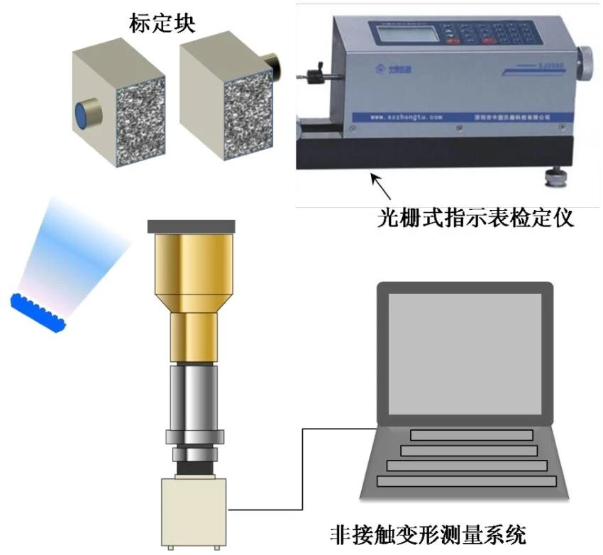
Schematic diagram of the room-temperature DIC calibration device
3.1 Hardware Configuration for Verification
Metrological Standard: Grating-based dial indicator calibrator (resolution ≤ 0.1 μm; certified by a metrology institute);
Calibration Fixtures: Two coplanar speckle calibration blocks (surfaces coated with high-contrast, uniform speckle patterns to meet DIC image correlation requirements);
System Under Test: Binocular 3D DIC measurement system (cameras, lenses, image acquisition software, and analysis algorithms);
Auxiliary Equipment: Temperature-controlled laboratory (20 ± 1°C, humidity ≤ 70%, to eliminate thermal drift interference).
3.2 Accuracy Verification Procedure (Indication Error Calibration)
Fixture Installation: Secure the two speckle calibration blocks to the movable and fixed ends of the grating calibrator, respectively; ensure the blocks remain coplanar and set a fixed gauge length *L*;
Strain Gradient Setup: Control the grating calibrator to drive the movable end and set 10 equidistant displacement increments; for each displacement increment ΔL, calculate the theoretical standard strain using the formula ε = ΔL/L; the range covers small (50 με), medium (500 με), and large (2000 με) strains, fully simulating the strain range across the fatigue cycle of composite materials;
DIC Data Acquisition: Once the displacement stabilizes at each increment, continuously capture 20 speckle images; use the software to calculate the full-field average strain between the two calibration blocks;
Error Calculation: Compare the measured DIC strain (ε_meas) with the standard grating strain (ε_std); calculate the absolute strain error Δε = |ε_meas - ε_std| and the relative error δ = (Δε / ε_std) × 100%;
Classification Assessment: If errors at all increments meet the Class B-1 criteria (absolute strain error ≤ 0.0001, relative indication error ≤ 0.5%), the equipment is deemed to have reached the required grade for aerospace composite material testing.
3.3 Precision (Repeatability) Verification Procedure
Select three representative strain levels (low, medium, and high strain);
Perform two complete "loading-unloading-reset" cycles for each level, collecting 15 sets of strain data per cycle;
Calculate the standard deviation of the data sets for each level; a lower standard deviation indicates higher measurement precision;
Industry compliance standard: For Class B-1 DIC systems, the repeatability standard deviation at a given strain point must be ≤20 με to meet the requirements for stable, long-term data acquisition during cyclic fatigue testing.
3.4 Verification Report and Metrological Certificate
Upon completion of the full gradient strain verification, compile the absolute error, relative error, and repeatability standard deviation for each level and issue a classification report in accordance with ASTM E83; institutions with Class I metrological qualifications may issue a certificate of conformity for the DIC equipment based on this method.
IV. Key Advantages of This Standardized Verification Method over the Traditional Rigid-Body Translation Method
Verifies actual strain and covers all operating conditions: The 10-level gradient strain fully simulates the fatigue process of composite materials—from micro-damage to large deformation—overcoming the limitations of rigid-body translation methods, which involve no strain and cannot assess measurement precision for small strains;
Higher metrological reference precision: The grating-based calibrator provides a 1 μm-level displacement reference, far superior to rigid-body translation fixtures using guide rails or scales, with errors that are traceable;
Simultaneous verification of both accuracy and precision: While traditional rigid-body translation measures only displacement deviation, this method simultaneously captures indicated value error and data repeatability, fully aligning with extensometer metrology standards;
Compatible with all DIC equipment types (2D/3D): The fixture supports both planar and stereo (binocular) DIC systems, offering strong versatility and compatibility with domestic 3D speckle measurement systems.
V. Engineering Application Value: The Necessity of DIC Verification in Composite Material Fatigue Testing
Under cyclic fatigue loading, early-stage damage in carbon fiber and glass fiber composites produces only micron-scale local strain anomalies; single-point measurements using strain gauges often miss critical damage signals, leading the industry to widely adopt 3D DIC for full-field strain acquisition throughout the testing process. If DIC equipment does not undergo standardized accuracy verification, the following engineering risks arise:
Distortion in strain measurement (50–100 με) during the micro-crack initiation stage, rendering the system unable to detect early-stage interfacial debonding;
Poor data repeatability in long-term cyclic fatigue tests, making results from different test batches incomparable;
Lack of metrological traceability for testing reports on aerospace and defense materials, preventing them from passing third-party reviews.
By adopting the standardized verification protocol using the grating-based calibrator described in this paper—and upon achieving Class B-1 verification—full-field strain data gain legal metrological validity. This enables the comprehensive recording of quantitative data across the entire lifecycle of crack initiation, propagation, interlaminar delamination, and component failure, thereby significantly enhancing the credibility of composite material fatigue testing.
VI. Summary and Industry Outlook
The key challenge in advancing DIC industry standardization is the lack of a practical, multi-gradient strain verification process. Drawing on established metrological systems for extensometers, this paper proposes an integrated method for verifying both accuracy and precision in room-temperature DIC systems using a high-precision grating-based displacement reference; this approach effectively eliminates the inherent flaws associated with rigid-body translation verification methods.
This protocol is already being applied to the periodic metrology of DIC measurement systems and can be extended to universities, third-party testing agencies, and automotive material laboratories. As DIC metrology standards are implemented, standardized DIC equipment is poised to fully replace traditional strain gauges and extensometers, becoming the standard optical measurement instrument for high/low-temperature, cyclic fatigue, and impact mechanics testing of composite materials.





















