summary
Many materials mechanics laboratories, after purchasing 3D DIC systems, lack standardized verification procedures. When conducting calibration of grating-type indicator instruments independently, they encounter problems such as incorrect tooling setup, unreasonable strain gradient settings, errors in error calculation logic, and missing reporting indicators, resulting in invalid calibration results that cannot be used for data traceability in cyclic fatigue testing of carbon fiber composites. This article, based on the "Accuracy and Precision Verification Methods for Digital Image Correlation Devices," introduces the entire verification process of room temperature grating tooling DIC step by step, covering general operating specifications for 2D/3D stereoscopic DIC equipment. This helps laboratories independently complete periodic metrological verification of DICs, reduces the cost of third-party testing, and ensures the metrological compliance of strain data measurement across the entire field of composite fatigue testing.
I. Preparatory work for DIC verification (avoiding the prerequisite of invalid verification)
Before conducting accuracy and precision verification of the DIC (Digital Index) instrument, four preliminary verifications must be completed. Failure to meet the standards for any one of them will directly lead to distorted verification data:
1. Environmental condition verification: The laboratory is kept at a constant temperature of 20±1℃, with a temperature fluctuation of ≤0.5℃ per hour, a relative humidity of 40%~70%, and no air convection or direct sunlight, to eliminate image noise caused by temperature drift and airflow disturbance;
2. Verification of metrological reference equipment: The grating indicator calibrator shall be certified by the Metrology Institute and the displacement error shall be ≤1μm. If the reference equipment expires, the entire verification result shall be invalid.
3. DIC system hardware self-test: Clean lens dust, check camera bracket rigidity (bracket displacement < 0.1μm under 1N external force), adjust light source to ensure speckle image grayscale contrast difference Δ > 50, no image overexposure or dark spots; binocular 3D DIC completes camera calibration in advance, calibration reprojection error ≤ 0.05 pixels;
4. Calibration block speckle quality verification: The speckle on the surface of the two calibration blocks is uniform, the black and white contrast is high, there are no large areas of blank space or paint peeling, the speckle size matches the DIC sub-region calculation requirements, and the image correlation calculation confidence level is >0.95.
After the preliminary preparations are completed, the entire calibration device is set up according to the standard schematic diagram: the grating calibrator is fixed on the vibration damping test bench, two speckle calibration blocks are fixed on the fixed end and the moving end of the calibrator respectively, the binocular DIC camera is facing the plane of the calibration block, the camera is perpendicular to the calibration block without tilt, and the field of view completely covers the measurement area of the two calibration blocks.
II. Key Operational Points for Tooling Setup and Gauge Setting
1. The two calibration blocks are parallel and coplanar with no height difference. Use a high-precision micrometer to measure the reference distance between the two calibration blocks and record the actual physical gauge length L (recommended gauge length 50mm/100mm, which is commonly used for matching composite material fatigue specimens).
2. The displacement direction of the grating calibrator is completely aligned with the direction of the line connecting the two calibration blocks to avoid introducing additional strain errors due to off-surface displacement;
3. The DIC field of view retains only two calibration block speckle regions and crops irrelevant backgrounds to reduce image computation noise;
4. The camera aperture and exposure parameters should be kept fixed throughout the entire calibration process. The lens, light source, and camera position must not be adjusted during the entire calibration process to prevent calibration failure.
III. Step-by-step practical operation of accuracy (indication error) verification (core link)
3.1 Gradient strain setting (fitting the full strain range of composite material fatigue)
The control grating calibrator's moving end is set with 10 equally spaced displacement levels, with uniformly distributed displacement increments, covering small strains of 50με, medium strains of 500με, and large strains of 2000με. This fully simulates the entire strain range of carbon fiber composite materials from microcrack initiation to crack expansion and delamination failure, avoiding biased calibration caused by only verifying a single strain.
3.2 Image Acquisition Specifications
After each displacement setting is stabilized and held still for 30 seconds to eliminate mechanical creep, 20 speckle images are continuously acquired. The DIC software is used to calculate the average strain across the entire area between two calibration blocks and output the measured strain ε. The acquisition parameters cannot be adjusted midway through the acquisition process for the same displacement setting.
3.3 Error Quantification Calculation (Core Data in the Verification Report)
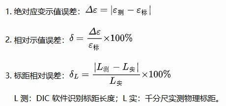
3.4, B-1 level accuracy judgment criteria
· All 10 strain gauges simultaneously meet the following requirements:
· The relative error of the gauge length δL ≤ 0.25%;
· Absolute strain indication error Δε≤0.0001 (100με);
· The relative indication error δ ≤ 0.5%;
· Absolute strain resolution ≤ 0.00005 (50 με).
If any setting exceeds the limit, the equipment's accuracy is deemed to be below B-1 level, requiring recalibration of the camera and repair of the lens before recalibration.
IV. Step-by-step practical operation of accuracy (repeatability) verification
Accuracy characterizes the stability of multiple measurement data from the DIC system, which is a key indicator for long-term cyclic fatigue testing. The operation procedure is as follows:
Three typical strain levels were selected from the 10 strain levels: low strain (100με), medium strain (800με), and high strain (1500με).
For each gear, perform two complete loading cycles: zeroing → loading to the target displacement → stabilizing and acquiring 15 sets of images → unloading and resetting;
Summarize 30 sets of measured strain data at the same grade and calculate the standard deviation σ.
B-1 Level Qualification Standard: σ≤20με under room temperature conditions; exceeding the standard deviation indicates large system measurement dispersion, severe fluctuations in strain data during long-term fatigue testing, and inability to accurately capture the strain of slowly expanding microcracks.
V. Summary Table of Verification Data and Grading Judgment (Required for Report)
After the verification is completed, organize the Excel data table, which includes the following fields: gear number, grating displacement ΔL, theoretical strain ε, measured strain ε of DIC, absolute strain error Δε, relative error δ, repeatability standard deviation σ, and individual judgment results. Finally, summarize the overall classification conclusion (Grade A/B-1/B-2/C/D).
VI. Complete Preparation Standards for DIC Verification Reports (Containing Essential Elements for Metrological Validity)
Laboratory self-calibration records and third-party metrology certificates must include the following core information; if any one of them is missing, the report is invalid and cannot be used for archiving composite material fatigue testing:
1. Basic Information: DIC equipment model, camera resolution, calibration date, ambient temperature and humidity, calibration personnel;
2. Metrological reference information: model of the grating indicator calibrator, metrological calibration certificate number, and validity period;
3. Tooling parameters: gauge length L of calibration block, speckle type, image acquisition parameters;
4. Complete calibration data: All error data and repeatability standard deviation data for 10 levels of gradient strain;
5. Grading criteria: Referenced standards ASTM E83, JJG 762, and ASTM E2208;
Final conclusion: The equipment achieves XX level accuracy and is suitable for testing conditions (room temperature 20±1℃).
Attachments: Actual photos of the calibration device, sample DIC strain cloud diagram, and a copy of the calibration certificate for the grating equipment.
VII. Verification of High-Frequency Errors in Practical Operation and Correction Plans
Rigid body translation without gradient strain verification: Correction: Setting 10 tensile strain levels, rigid body translation cannot verify strain indication error;
Camera lens/light source adjustment midway: Correction: Keep optical parameters fixed throughout the process. After adjustment, complete recalibration and verification from the beginning are required.
Ignoring gauge length error calculation, only verifying displacement error: Correction: Gauge length error is a Level 1 indicator of ASTM E83; if it is missing, Level B-1 cannot be determined.
Insufficient image acquisition quantity, high data noise: Correction: Acquire at least 20 images per range and average them to reduce random measurement error;
Uncontrolled ambient temperature fluctuations: Correction: Allow the sample to stand in a constant temperature laboratory for 2 hours before conducting the test to avoid spurious strain caused by temperature drift.
VIII. Recommendations for the Management of Laboratory DIC Verification Cycles
Commercial third-party metrology: Submission for testing every 12 months, issuance of a statutory metrology certificate;
Laboratory-based autonomous grating fixture self-inspection: A complete accuracy and precision verification is conducted every 6 months;
Temporary verification scenarios: Before replacing lenses, adjusting camera brackets, repairing equipment damaged by impacts, or conducting major special composite material fatigue tests, immediate re-verification is required to confirm that the accuracy remains at level B-1.
IX. Conclusion
The grating-type extensometer calibration instrument offers a standardized and practical operational procedure for room temperature DIC metrological verification. From environmental preparation, tooling setup, gradient strain loading, data calculation to calibration report preparation, each step has clearly defined quantitative specifications. Once the materials laboratory masters the entire operational method, it can independently complete the periodic accuracy calibration of the 3D DIC system, significantly reducing the cost of third-party metrological testing while ensuring that the material test data has complete metrological traceability and that the test report meets the requirements for materials testing metrological audit. The entire calibration process strictly adheres to the ASTM E83 B-1 extensometer standard and represents a standardized metrological operational solution for DIC equipment.





















