I. DIC Technology: Visualizing the Compression-Induced Deformation Process
Irregularly shaped components are widely used in fields such as equipment manufacturing, precision structural engineering, and new material development. Their deformation behavior and strain distribution under compression directly determine the overall structural safety and operational reliability. These components often feature geometrically asymmetric structures, making them prone to coupled bending-torsion deformation and stress concentration when subjected to axial compression. Traditional measurement methods struggle to mount sensors on curved surfaces or open-lattice structures; furthermore, they fail to characterize full-field deformation or capture critical phenomena such as localized high strain, shear bands, and damage propagation.
In this study, the XTOP3D XTDIC 3D full-field strain measurement system was employed to conduct quasi-static compression tests on irregular components. The system enabled the visualization and analysis of full-field displacement and strain distributions on the specimen surface. This approach facilitated the assessment of overall deformation uniformity, the localization of high-strain regions, the observation of shear band formation and propagation, and the tracking of damage evolution, thereby providing reliable data to support the mechanical performance evaluation, structural optimization, and failure mechanism analysis of irregular components.
II. Challenges in DIC Measurement of Lattice-like Complex Components
Given the use of binocular DIC cameras and the constraint of observing only the external surface, measuring lattice-like complex components presents several challenges due to characteristics such as fine, intricate ribs, dense curved surfaces, and numerous open-work edges.
1. Difficulty in matching fine lattice units: Due to the small dimensions of ribs and apertures, fixed-size computational subsets may span across different regions, leading to the loss of measurement points and anomalous strain readings.
2. Out-of-plane displacement causing pseudo-strain:Undulating curved surfaces on the lattice undergo significant out-of-plane displacement under compression; this can be misidentified as strain, resulting in data distortion.
3. Speckle tracking and edge errors: Speckle uniformity is poor on the narrow surfaces of the lattice, and speckles tend to blur in regions of large deformation; abrupt pixel changes at open-work edges can lead to computational errors.
III. Technical Support for XTDIC System Adaptability
The XTDIC 3D full-field strain measurement system employs a non-contact measurement method that does not alter the component's original loading state, allowing for the accurate reconstruction of its true deformation behavior.
3D calculation to suppress pseudo-strain
Leveraging binocular 3D DIC principles, the system independently distinguishes between in-plane and out-of-plane displacements and corrects for surface projection distortion. This addresses the issue of pseudo-strain on curved lattice surfaces at the fundamental level, ensuring the authenticity of the strain data.
Adaptive subsets for fine lattice structures
A variable computational subset algorithm is used to automatically adjust window sizes based on lattice unit dimensions and local topography. This prevents calculations from spanning across ribs or apertures, thereby improving the matching success rate for fine structures.
Image and edge optimization
Image enhancement techniques are used to optimize speckle features on lattice edges and curved surfaces. Combined with edge error correction algorithms, this reduces computational bias at the edges of open-work apertures and enables precise identification of stress concentration zones within the lattice.
IV. Test Plan and Measurement System
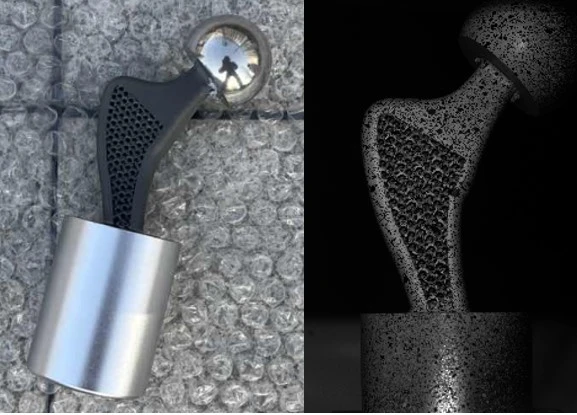
Specimen Overview
The object of this test is a complex component subjected to compression (featuring an exposed lattice structure). The test aims to acquire 3D displacement and principal strain distributions on the specimen's outer surface under axial compressive loads, identify regions of concentrated deformation, and reveal the component's mechanical response characteristics under compression. Testing Equipment and Setup
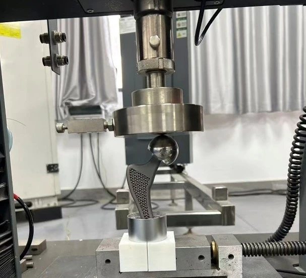
Loading equipment: Electro-hydraulic servo universal testing machine
Measurement system: XTOP3D XTDIC 3D full-field strain measurement system
Environmental conditions: Room temperature; absence of significant vibration or airflow interference to ensure stable image and load data
Specimen preparation: The specimen surface was sequentially coated with a matte white base layer and a high-contrast random speckle pattern to enhance image matching and calculation accuracy.
Loading and Measurement Parameters
Loading mode: Displacement-controlled quasi-static compression
Compression speed: 0.5 mm/min
Loading termination: Unloading initiated when the load reached approximately 2300 N
Synchronous acquisition: The XTDIC system was synchronized with the testing machine to simultaneously capture external surface images, load data, and displacement data, ensuring temporal alignment across multi-source datasets.
V. DIC Reveals Typical Deformation Modes of Complex-Shaped Components Under Compression
The XTDIC 3D full-field strain measurement system reconstructs the complete deformation path of the component through continuous strain and displacement contour maps. For complex-shaped components featuring an exposed grid-like structure, the system clearly visualizes anisotropic mechanical behavior and deformation characteristics. By outputting displacement curves for key points, full-field displacement contours, and principal strain contours, it comprehensively captures the magnitude and mode of deformation, as well as the triggers for instability.
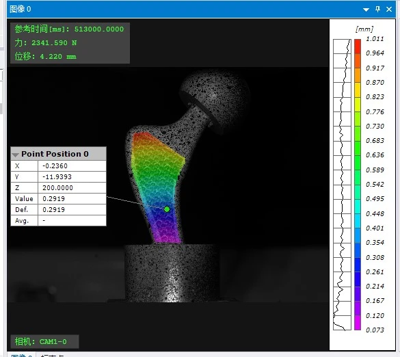
1. Displacement response at key points
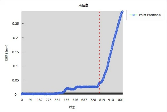
Displacement-load curves were extracted from representative measurement points on the specimen. The displacement at these points increased steadily as loading progressed; the curves showed no abrupt changes or fluctuations, indicating stable test conditions. Upon reaching the target load, the displacement at the measurement point was 2.783 mm; the XTDIC system accurately captured this minute deformation using sub-pixel algorithms. The relationship between displacement and load was linear, consistent with Hooke's Law, demonstrating that the specimen underwent primarily elastic deformation within this loading range and did not enter the plastic yielding stage.
Displacement of key points selected via DIC software:
2. Distribution of Total Displacement Across the Entire Field
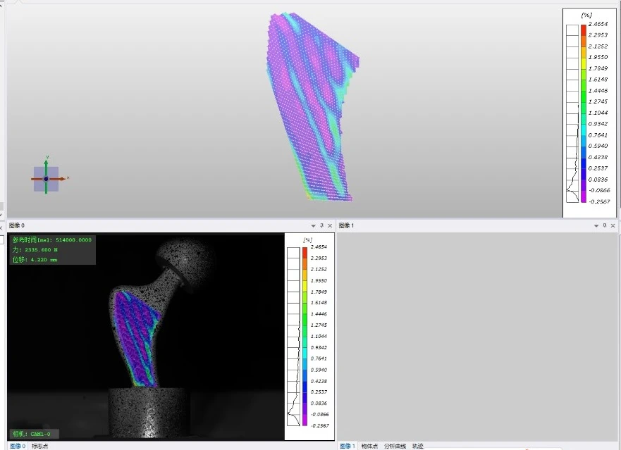
The 3D total displacement contour map reveals that the deformation of the complex-shaped component under compression is asymmetric and non-uniform. Regions of high displacement are concentrated at the loading contact surface, the structural transition section, and the junctions of the grid ribs; the maximum total displacement across the entire field is 4.220 mm. Displacement gradients intuitively reflect load transfer paths and variations in local stiffness, enabling the rapid identification of structurally weak areas. This single-viewpoint measurement fully covers the visible exterior surface of the specimen with no effective measurement blind spots, comprehensively capturing the deformation characteristics of both the grid structure and the complex curved surfaces.
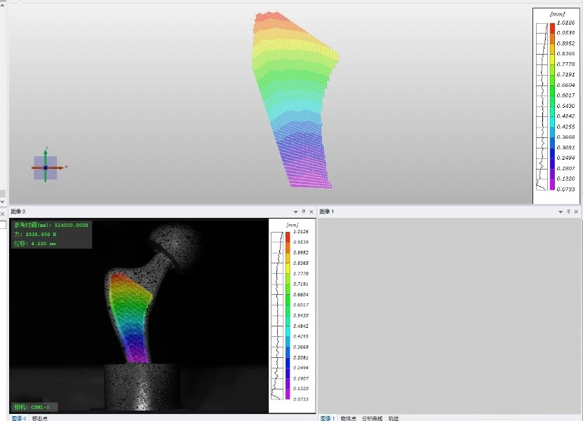
Corresponding operating parameters: load of 2335.600 N and maximum total displacement of 4.220 mm.
3. Full-field principal strain distribution
Several distinct regions of strain concentration are observed on the visible surface of the specimen. These locations coincide closely with geometric discontinuities, cross-sectional changes, the edges of grid apertures, and rib intersections. The maximum principal strain reaches 2.4654%; the high-strain zones are localized with steep gradients, exhibiting characteristic features of stress concentration. Both tensile and compressive strains coexist across the field, clearly delineating the loading state and providing a basis for predicting the risk of structural failure. Notably, the edges of the grid cutouts and the roots of the ribs are identified as zones of high strain and are also the locations most susceptible to structural damage.
VI. Summary of Deformation and Mechanical Behavior
1. The compressive deformation of irregularly shaped components and exposed lattice structures exhibits a spatially non-uniform distribution; displacements and strains concentrate at geometric discontinuities, lattice intersections, and open-cell edges, identifying these as the primary potential failure zones.
2. The binocular 3D DIC system accurately captures minute deformations and localized high-strain regions on visible surfaces, overcoming the limitations of incomplete data associated with traditional point-based measurement methods.
3. The experimentally obtained full-field displacement and strain data are highly standardized, enabling direct application in finite element model calibration, structural stiffness assessment, and lattice layout optimization.
VII. Experimental Conclusions
The XTOP3D XTDIC 3D full-field strain measurement system utilizes binocular DIC cameras to perform non-contact, high-precision dynamic measurements on the visible surfaces of irregularly shaped components, effectively resolving issues related to difficult sensor placement and incomplete data inherent in traditional measurement techniques.
1. The full-field displacement and principal strain maps obtained from the experiments allow for the accurate identification of strain concentration zones and structural weak points in irregularly shaped components and lattice structures, providing a quantitative basis for structural optimization.
2. Addressing the specific structural and deformation characteristics of lattice-based irregular components, the XTDIC system employs technologies such as 3D reconstruction, adaptive algorithms, and edge optimization. These effectively overcome challenges—including pseudo-strain on curved surfaces, issues arising from fine lattice elements, and edge measurement errors—to reliably analyze full-field displacement and strain across lattice surfaces.
3. The XTDIC system enables the synchronized acquisition of load, displacement, and strain data, meeting the requirements for material property testing, structural mechanics analysis, and failure mechanism research. It offers significant value for mechanical testing and safety assessment of irregularly shaped and lattice-structured components, serving as a preferred solution for mechanical testing of complex structures.