The application of new materials in automotive body structures and safety components is a primary strategy for achieving vehicle lightweighting. Combining high strength—derived from phase-transformation effects—with high formability is crucial for the high-performance manufacturing of automotive parts.
However, these novel materials exhibit vastly different hardening behaviors under varying loading conditions, and sheet metal often undergoes complex strain paths during the forming process. These factors pose new challenges and requirements for existing mechanical characterization methods and classical constitutive models. Consequently, there is an urgent need for advanced characterization techniques capable of precise measurement and accurate description, enabling the analysis of various defects in the stamping process—such as wrinkling, springback, necking, and fracture.
Based on Digital Image Correlation (DIC) technology, the XTOP3D XTDIC 3D full-field strain measurement system records the complete deformation history of materials and provides detailed information on surface strain distribution. It enables the assessment of material formability and provides appropriate metrics for evaluating formability based on the DIC method.
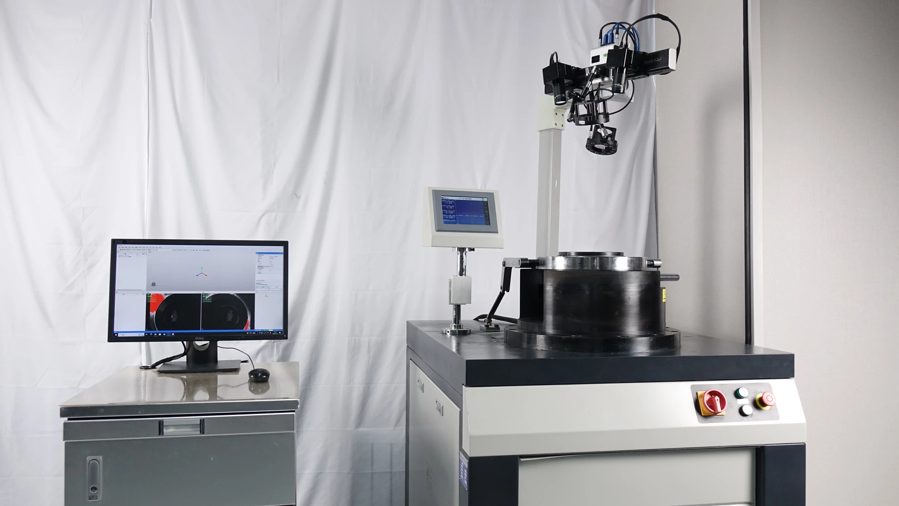
In the stamping production of automotive components, the forming limit is a critical parameter; it represents the maximum deformation a sheet metal can undergo before the onset of plastic instability and serves as a key basis for determining the feasibility of various forming processes.
Forming limits play a vital role in sheet metal forming and stamping processes, specifically in the following areas:
(1) Evaluating the local formability of sheet metal;
(2) Assessing the feasibility of die designs and stamping processes;
(3) Addressing material selection and blank determination;
(4) Monitoring stamping production;
(5) Detecting sheet metal instability in numerical simulations.
Analyses of the Forming Limit Curve (FLC) are based on material yield criteria and plastic constitutive relationships, utilizing tensile instability criteria to determine the onset of necking or fracture. However, due to the limited applicability of each criterion, discrepancies often arise between theoretical calculations and experimental results.
By employing the XTOP3D XTDIC 3D full-field strain measurement system in conjunction with Nakazima forming tests, Digital Image Correlation (DIC) technology enables dynamic monitoring of the stamping process. This allows for the analysis of instantaneous global surface displacement and strain fields in automotive sheet metal, as well as precise assessment of the limiting states associated with local necking.

Experimental Scheme for Sheet Metal Forming Limits
The Nakazima test method is employed, in which a punch presses against a gridded sheet until necking or fracture occurs. As the punching process alters the sheet's dimensions, the XTDIC 3D full-field strain measurement system monitors the strain state in real time; subsequent analysis using DIC software yields the limiting strains for various strain paths, enabling the construction of a complete Forming Limit Curve (FLC).
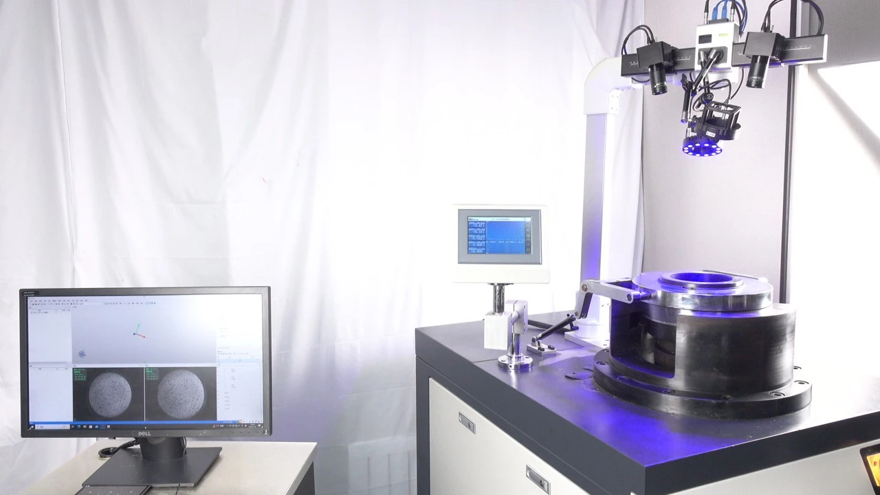
The upper unit of the punch stamping testing machine is open to facilitate image acquisition by the XTDIC 3D full-field strain measurement system; additionally, an interface is reserved on the testing machine platform to allow for the mounting of a cantilever beam mechanism, enabling the XTDIC system—in conjunction with the cantilever beam—to capture images from above and ensure the smooth conduct of the experiment.
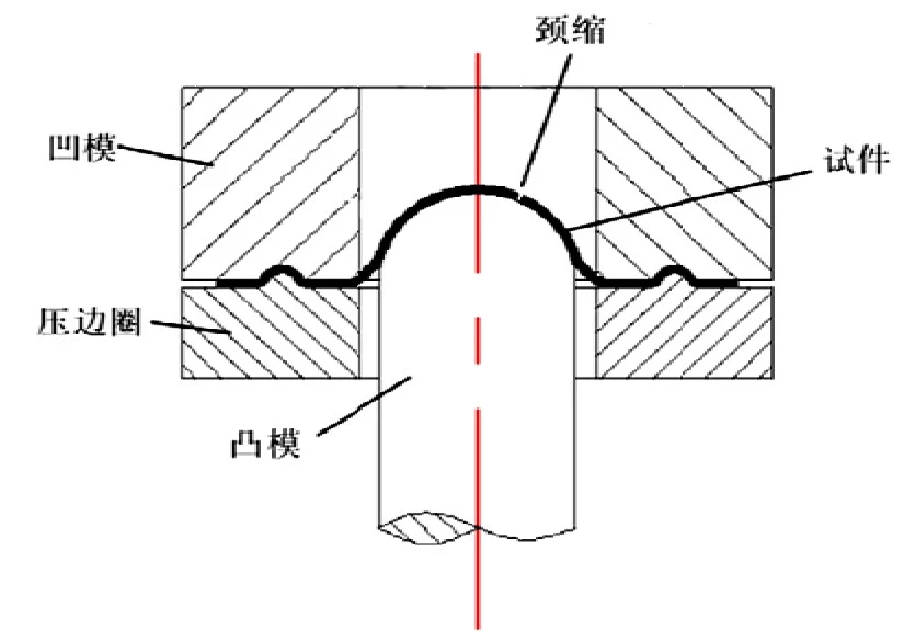
Experimental Procedure
The test specimen consists of an alloy material with a thickness of 2 mm; it was machined in accordance with national standards, and a speckle pattern was prepared on its surface.
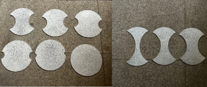
Setup of the DIC Measurement System
Mount the main unit of the XTDIC 3D full-field strain measurement system onto the cantilever beam. Apply grease to the top of the spherical head and the back of the specimen; then, place a piece of film—fully coated with grease—onto the surface of the spherical head to create a dual-lubrication effect, and finally position the specimen on the experimental platform.
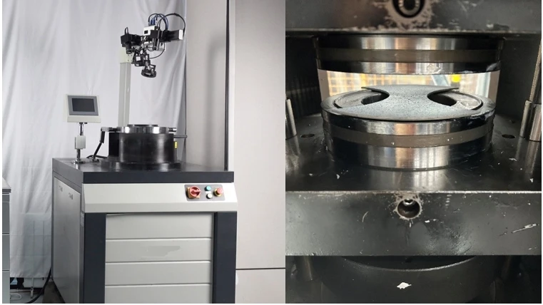
Data Acquisition Setup
In the experiment, the blank holder force was set to 200 kN and the punch speed to 1 mm/s; the XTDIC 3D full-field strain measurement system captured data at a rate of 20 frames per second. Data acquisition commenced upon contact between the hemispherical punch and the specimen and continued until failure.
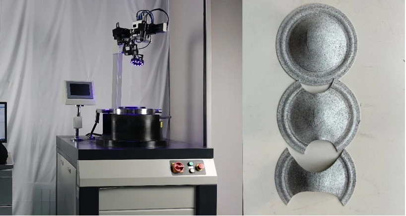
Analysis of Experimental Data
Upon completion of data acquisition, the DIC software accompanying the XTDIC 3D full-field strain measurement system automatically generates 3D deformation contour maps, including the surface morphology, out-of-plane displacement field, and principal strain field at the point of critical fracture. By selecting the "profile line" function within the DIC software, one can draw a profile line perpendicular to the crack, plot the corresponding curve, and determine the forming limits of the sheet metal.
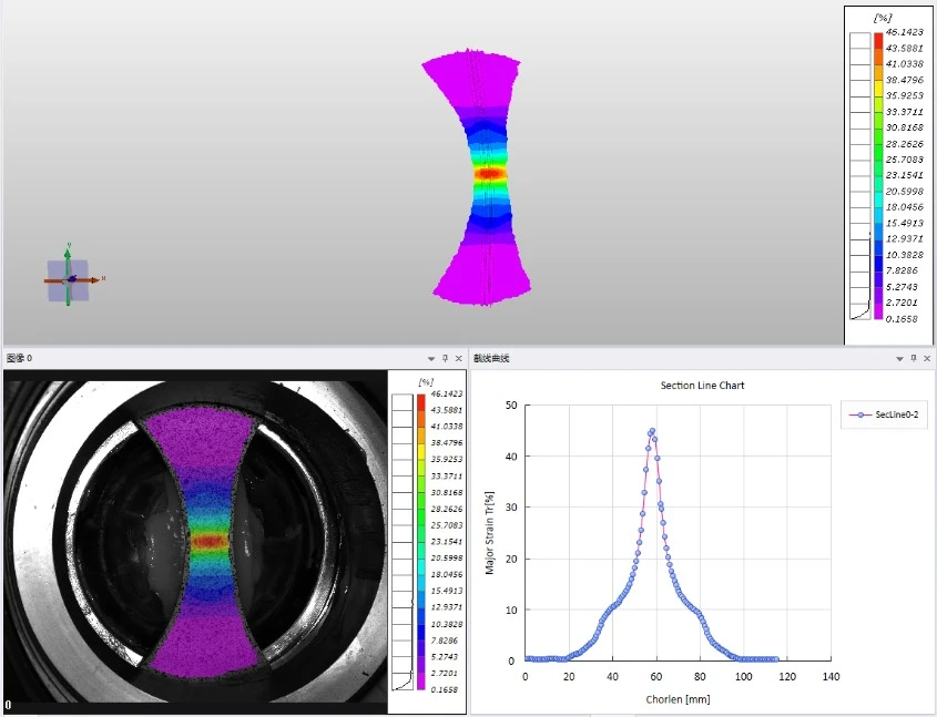
The XTOP3D XTDIC 3D full-field strain measurement system is applied in the field of material forming limit analysis. It eliminates the need to predict fracture locations in advance and enables the simultaneous measurement of strain components across multiple directions. The system automatically extracts key data points to generate major-minor strain curves and is suitable for measuring forming limit data under both linear and non-linear strain paths.
DIC technology provides precise experimental data that assists the automotive industry in optimizing structural design and material selection; this effectively reduces product weight while maintaining or enhancing performance and safety.





















