In the injection molding industry, quality control for small, complex, and high-precision plastic parts is crucial yet presents significant challenges. First, complex geometries—such as thin walls, apertures, and snap-fits—complicate inspection, making it difficult for traditional measuring equipment to meet requirements. Second, tight tolerances demand high precision; features like mating surfaces and mounting holes require strict adherence to dimensional, positional, and profile specifications. Third, batch inspection processes are time-consuming and costly, while also relying heavily on the operator's experience, leading to significant result variability.

Equipment Selection: Blue-light 3D Scanning Solution
The injection-molded plastic part in this case is compact, featuring multiple precision snap-fits, locating holes, thin-walled structures, and small-radius fillets; consequently, strict control over overall profile deformation and critical dimensional accuracy is required.
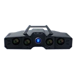
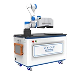
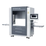
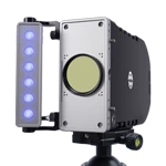
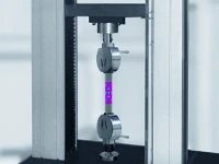
The XTOP3D XTOM blue-light 3D scanner is utilized, featuring a scanning head designed for small-to-medium fields of view (approximately 100–300 mm) and paired with a high-precision motorized rotary table. For parts with complex geometries or deep holes, seamless multi-angle scanning from any position—eliminating blind spots—can be achieved by pre-applying reference markers to the rotary table or using an auxiliary reference frame.
")
Breakdown of the Practical 3D Scanning Workflow
This case study focuses on the comprehensive quality inspection of a single injection-molded plastic part, utilizing a workflow that is simple and easy to master.
01 Part Preparation and Positioning
Place the injection-molded part securely in the center of the scanner's turntable, ensuring it is stable and free from wobbling. If the part features deep holes or reflective surfaces, apply a thin layer of developer spray beforehand (this will not affect dimensional accuracy).
02 Parameter Setting and Path Planning
Configure the settings in the software interface based on the part's dimensions and complexity:
-
Scan resolution (select high definition for high-detail requirements).
-
Turntable rotation angle (choose multiple angles to minimize blind spots).
-
Targeted high-precision scanning for specific areas of interest on the part.
03 Data Acquisition and Reconstruction
Initiate the scan. The XTOM blue-light 3D scanning system captures images from multiple angles (involving part flipping for multi-sided data acquisition), while blue-light fringe projection precisely captures 3D surface point cloud data. The XTOM 3D scanning software stitches the data from various angles in real-time, generating a highly complete 3D model (STL file) of the plastic part.
")
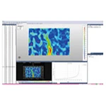
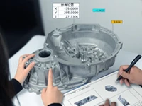
Global 3D Deviation Analysis of Injection-Molded Parts
Clearly displays maximum ± deviations and the distribution of out-of-tolerance areas; analyzes localized material accumulation, shrinkage, or structural collapse.
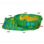
Typical out-of-tolerance points:
Point 3: +1.0773 mm; noticeable bulging in the snap-fit area
Point 10: +0.5206 mm; protrusion on the mounting surface
Point 14 (CMP1 area): -1.6174 mm; insufficient material at the bottom of the deep cavity
Positional deviation analysis:
Positional deviation 1: Mounting hole misalignment; potential for assembly interference
Line 1 positional deviation: Tilt in the overall structural flatness


Targeted Analysis of Local Features
1. High-Stress Area (CMP1)
Points of concentrated deformation: Predominantly negative deviation at the deep bottom cavity and corners → Uneven material shrinkage (packing process requires optimization)
2. Assembly Surface Area (CMP2)
Overall positive deviation: Flash at the parting line or mold wear
Peak deviation: Affects sealing performance
3. Rib Area (CMP3)
Uniform negative deviation: Sink marks caused by excessive cooling rates