The main feedwater pump is essential equipment in a nuclear power plant; its normal operation ensures a steady water supply to the steam generator and plays a crucial role in the safe, stable operation of the unit and in nuclear safety.
To investigate the dynamic behavior of the pump casing and motor across five stages—pump warming, startup, operation, shutdown, and cooling—the XTOP3D XTDIC-STROBE 3D dynamic measurement system was employed. This system was used to analyze deformation-induced misalignment during these stages, plot displacement and deformation curves for the pump casing, discharge pipe, and suction pipe, and identify the specific locations and sources of the deformation.
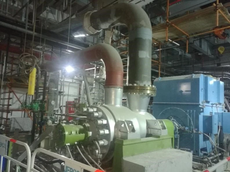
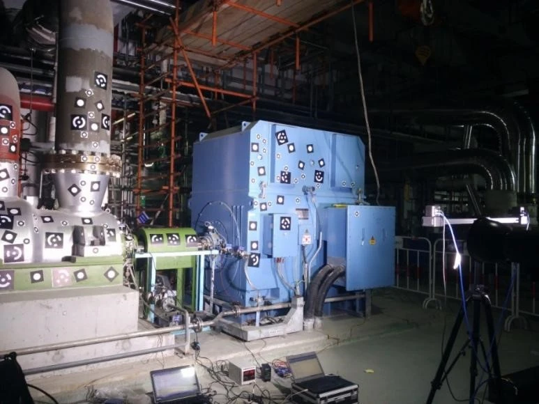
被测水泵与电机
Using the XTOP3D XTDIC-STROBE 3D dynamic measurement system, two high-speed cameras captured real-time images of the main feedwater pump and motor across various stages of deformation. Stereo matching was achieved through the accurate identification of markers to reconstruct the 3D spatial coordinates of points on the measured surfaces, enabling the calculation of data such as deformation magnitude and 3D trajectory/pose.
Experimental Procedure
Markers were affixed to the surfaces of the pump body, discharge pipe, suction pipe, and motor. The XTDIC-STROBE system was used to continuously capture images throughout the experiment; the coordinates and displacement data of the markers were calculated, and displacement-versus-time curves were plotted.
DIC measurement test site
DIC Test Data
Uniform sampling at a 1:12 interval was applied to over 87,000 data sets. The sampled images were processed to plot displacement curves for marker points on the surfaces of the pump body and motor, thereby identifying the stage at which misalignment occurred.
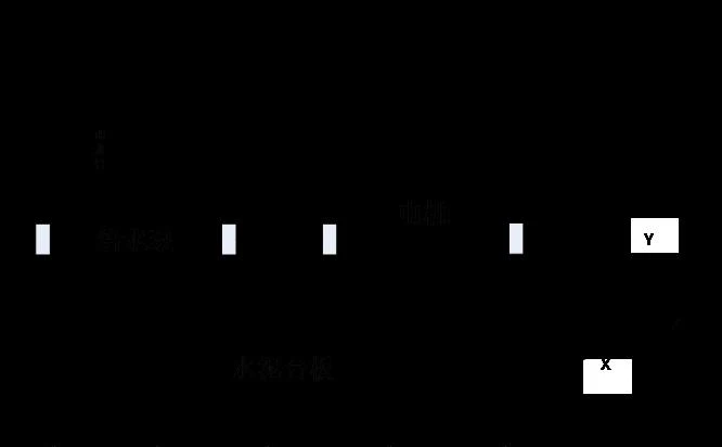
Diagram Showing Pump Coordinate Directions
Analysis of Pump Body and Motor Data
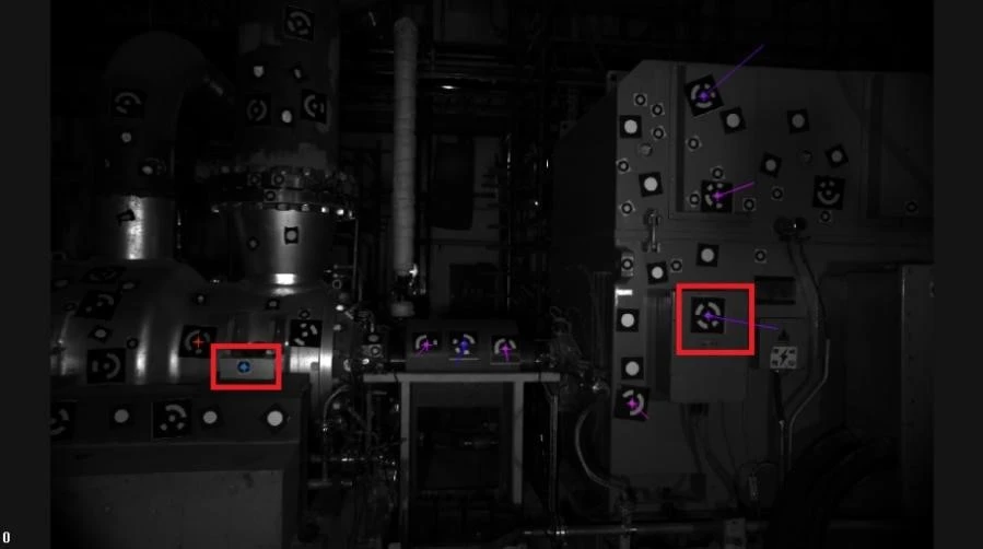
Analyze the marked points at key locations on the surfaces of the pump body and motor shown in the figure, and analyze the displacement curves of the selected points during the deformation process.
Selected points on the surfaces of the pump body and motor
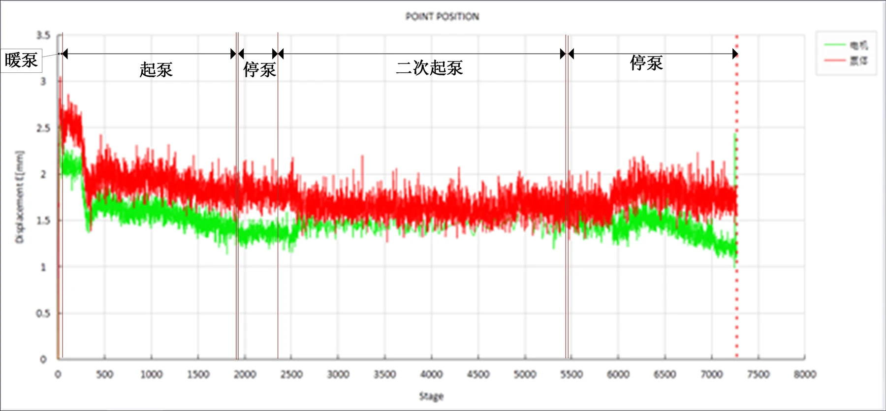
The total displacement curves for points on the surfaces of the pump body and motor, along with the division of experimental state intervals, are shown in the figure below.
Explanation of Total Displacement Curves for the Motor and Pump Body and Classification of Experimental States
The horizontal axis of the displacement plot represents the number of camera data acquisitions. Since the camera's acquisition frequency varies across different test stages, the following conversion factors are used to map these data points to actual time:
0–36 (Pump warming): Each interval corresponds to 12 minutes of actual time;
36–1800 (Pump startup): Each interval corresponds to 1.2 seconds of actual time;
1800–19300 (Steady state): Each interval corresponds to 12 minutes of actual time;
1930–2380 (Pump shutdown): Each interval corresponds to 1.2 seconds of actual time;
2380–5450 (Second startup): Each interval corresponds to 1.2 seconds of actual time;
5450–7340 (Second shutdown): Each interval corresponds to 1.2 seconds of actual time.
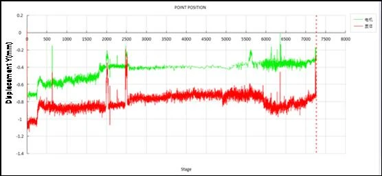
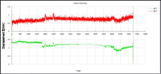
The figures below show the displacement curves for the pump body and the motor in the X, Y, and Z directions. The graphs reveal that, starting from the pump warming phase, the displacements of the pump body and the motor are inconsistent.
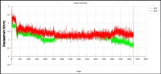
Pump body and motor displacement curves in the X-direction
Displacement curves of the pump body and motor in the Y-direction.
Z-direction displacement curves for the pump body and motor
X-direction: Both the pump casing and the motor shifted in the X+ direction. During the pump warming phase, the displacement was 2.3 mm for the pump casing and 1.9 mm for the motor, resulting in a displacement difference of approximately 0.4 mm.
Y-direction: At the start of the warming phase, both the pump casing and the motor shifted in the Y- direction, with a misalignment of 0.3 mm. The pump casing exhibited greater displacement; this Y-direction deviation persisted from the beginning through the end of the experiment, remaining relatively stable during the startup and operation phases and gradually narrowing during the shutdown phase.
Z-direction: The pump casing shifted in the Z+ direction while the motor shifted in the Z- direction. The magnitudes of displacement were essentially identical, and the process was relatively stable, with displacement values generally maintained between 0.5 mm and 1.0 mm.
Data analysis for the pump casing, discharge pipe, and suction pipe during the pump warming phase
For the warming phase, three relatively stable points on the surfaces of the pump casing, discharge pipe, and suction pipe were selected for data analysis; the locations of these points are shown in the figure below:
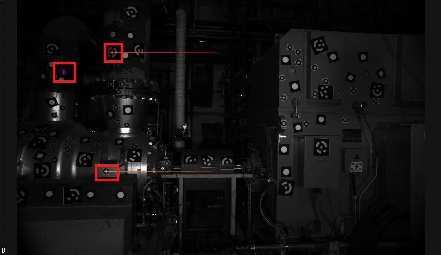
Selected measurement points on the surfaces of the pump body, inlet pipe, and elbow pipe using DIC technology.
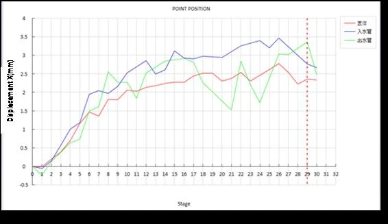
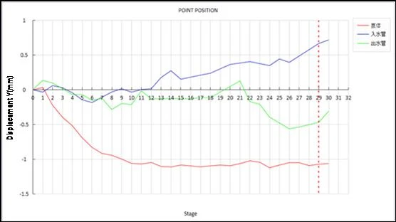
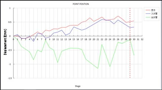
The curves showing the displacement of the pump body, inlet pipe, and outlet pipe in the X, Y, and Z directions over time are illustrated below; each state interval corresponds to an actual duration of 12 minutes:
Measurement of X-direction displacement curves for the pump casing, inlet pipe, and outlet pipe during the pump warming phase using DIC technology.
Y-direction displacement curves of the pump casing, inlet pipe, and outlet pipe during the pump warming-up phase measured using DIC technology.
Measurement of Z-direction displacement curves for the pump casing, inlet pipe, and outlet pipe during the pump warming phase using DIC technology.
Based on the displacement curves output by the 3D-DIC software, the following observations can be made regarding the pump warming phase:
X-direction: The pump body, discharge pipe, and suction pipe all move in the X+ direction; the displacement magnitudes are essentially uniform, approaching 2.5 mm.
Y-direction: The pump body moves in the Y- direction, with displacement gradually increasing and stabilizing at 1.1 mm after two hours of warming. The suction pipe moves in the Y+ direction, with displacement gradually increasing to a total of 0.7 mm by the end of the warming phase. The discharge pipe moves overall in the Y- direction during the process, with a total displacement of 0.3 mm by the end.
Z-direction: The suction pipe and pump body gradually move in the Z+ direction (0.3 mm and 0.5 mm, respectively), while the discharge pipe moves in the Z- direction by 0.5 mm.
Error Analysis
When measuring the pump body and motor using the XTDIC-STROBE 3D dynamic measurement system (based on 3D-DIC technology), the analysis indicates that experimental errors primarily stem from the following sources:
Camera Temperature Fluctuations
The DIC measurement process exceeds 10 hours. Prolonged operation causes the camera itself to heat up, leading to minute thermal warping or deformation in components such as the image sensor. This creates discrepancies between the camera's principal point and the initial calibration results, introducing noise into the measured data.
High-Temperature Heating of the Pump Body
During the experiment, the pump body surface reaches high temperatures, causing issues such as discoloration or wrinkling of the target markers captured by the 3D-DIC equipment. This introduces errors in marker tracking; while the 3D-DIC software selects stable data points for analysis, the high-temperature fluctuations inevitably introduce some noise.
Accuracy Assessment
Taking the aforementioned factors into account and analyzing the images captured by the 3D-DIC system, the overall measurement accuracy of the 3D-DIC equipment is assessed to be within 0.1 mm.
Experimental Conclusions
1) By utilizing the XTDIC-STROBE 3D dynamic measurement system in conjunction with high-speed cameras—which enable high resolution at high frame rates—the 3D-DIC software can analyze the displacement and deformation of the test object with greater clarity and precision. 2) Measurements of the pump casing and motor were conducted to analyze their deformation during the comprehensive testing phase; inconsistent deformation observed during the pump warm-up stage resulted in misalignment between the pump casing and the motor.
3) Analysis of the total displacement curves for points on the surfaces of the pump casing and motor—along with the segmentation of experimental operational intervals—reveals that their displacements were inconsistent throughout the testing process, starting from the warm-up phase.
4) Analyzing displacement and deformation data for the pump casing, motor, discharge pipe, and suction pipe facilitates the early detection of issues during commissioning and trial runs; this provides foundational data for subsequent analysis and system safety, thereby ensuring the safe operation of the unit.