In precision manufacturing sectors such as automotive, aerospace, and shipbuilding, studying the mechanical properties of thin-walled metal materials under high-temperature welding conditions is critical for ensuring machining precision, dimensional accuracy, and structural integrity; it is also a pressing issue in industrial production. Traditional contact-based measurement methods (such as dial indicators and strain gauges) are unable to capture the full process of transient thermal deformation or provide full-field strain data. Furthermore, optimizing welding process parameters requires data derived from dynamic, full-field deformation measurements.
The XTOP3D DIC solution for measuring welding deformation in thin metal sheets at high temperatures utilizes Digital Image Correlation (DIC) technology. By overcoming issues such as image "decorrelation" caused by thermal radiation, heat flow disturbances, and the degradation of speckle pattern quality at high temperatures, the system successfully measures deformation during high-temperature welding. It analyzes stress variation patterns in welded components to provide early warnings and a sound basis for assessment, thereby ensuring the quality of the welded parts.

Digital Image Correlation (DIC) technology is increasingly widely used at room temperature, and the measurement technique has become increasingly mature, enabling the successful measurement of deformations in various objects under ambient conditions. However, when measuring deformation during high-temperature welding, it is necessary to overcome high-temperature interference as the temperature rises in order to enhance the reliability of the measurement data.
Applying DIC technology to measure the deformation of metal materials during high-temperature welding requires overcoming the following technical challenges:
1. Preparation of high-temperature-resistant speckle patterns: High-temperature welding can damage surface features, causing speckle pattern matching to fail; therefore, a high-temperature-resistant speckle pattern must be created.
2. Mitigation of welding environment interference and image noise:Factors such as welding arc light, localized reflections from auxiliary lighting, and thermal radiation degrade speckle image quality, leading to calculation errors.
The XTOP3D XTDIC 3D full-field strain measurement system ensures measurement accuracy and data reliability during high-temperature welding deformation measurements through measures such as high-temperature-resistant speckle preparation and improved matching algorithms.
1. High-temperature-resistant speckle preparation: High-temperature-resistant digital speckle patterns are created to effectively overcome the "weak correlation" phenomenon.
2. Interference reduction:Optical filters of specific wavelengths and custom welding brackets/baffles are employed based on measurement requirements to effectively minimize interference from the welding environment.
3. Advanced matching and image processing:The XTDIC system utilizes matching algorithms designed for high-temperature, weak-correlation environments. Raw images undergo Gaussian smoothing to suppress Gaussian noise and enhance contrast, ensuring successful matching of image subsets during correlation calculations.
4. Handling degraded speckle quality: To address the degradation of speckle quality in the weld zone, the DIC software employs a stepwise matching algorithm. By leveraging the similarity between adjacent weakly correlated images, the system automatically establishes references within the image sequence. A piecewise adaptive reference-setting method ensures successful image matching while minimizing accuracy loss.
XTOP3D XTDIC 3D Full-Field Strain Measurement System Configuration:
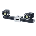
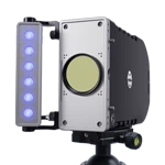
Hardware: Two high-speed CMOS cameras, a high-power LED speckle light source, and infrared filters (to eliminate interference from welding arc light).
Software: DIC software featuring real-time image acquisition and 3D displacement calculation algorithms (sub-pixel accuracy of 0.01 pixels).
Method: A high-contrast speckle pattern is sprayed onto the surface of the thin plate; full-field 3D displacement and strain fields are calculated by tracking the motion of speckle sub-regions.
Measurement of High-Temperature Welding Deformation in Thin Metal Sheets
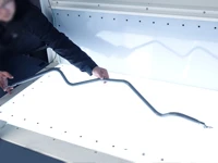
1. Pattern Application
Spray a high-temperature resistant matte paint onto the surface of the test specimen to create a white base coat, then apply a high-temperature resistant matte black spray paint to form a speckle pattern, as shown in the figure below:

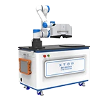
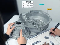
2. DIC Equipment Setup and Calibration
The XTDIC 3D full-field strain measurement system is installed beneath the welding test bench. The focal length and aperture of the DIC system's camera lenses are adjusted to ensure clear images with uniform brightness, and the internal and external parameters of the cameras are calibrated. As shown in the figure:

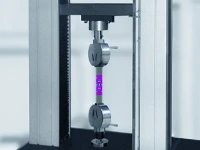
3. Image Acquisition
Once preparations are complete, capture images covering the entire process, from welding through to cooling. The figure shows an image of the welding operation in progress.

4. Analysis of Welding Strain Results
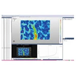
Using the XTDIC 3D full-field strain measurement system software, the calculation can be executed to automatically process image data and analyze the full-field displacement contour maps—characterized by a saddle shape—during the welding of thin metal sheets and after cooling. By selecting key points within the DIC software, displacement data curves for those points can be obtained.
Thermal Expansion Phase
Characteristics of the weld zone contour map: Under high-temperature heat input, the central region of the molten pool appears bright red (indicating the zone of maximum positive displacement in the Z-direction), with the magnitude of displacement decreasing gradually from the center toward the edges.
Typical phenomenon: An elliptical bulge forms with the weld seam as the axis of symmetry; the maximum displacement at the center reaches +1.7 mm, and the contour map exhibits a "volcanic crater" pattern of thermal expansion.

Solidification and Shrinkage Stage
Color map inversion: The center of the molten pool shifts abruptly from red to blue (with the displacement value plummeting from +1.7 mm to -0.6 mm), indicating that the solidification of the molten metal triggers longitudinal shrinkage.
Symmetrical red bands appear in the heat-affected zones on both sides, signaling the onset of warping.

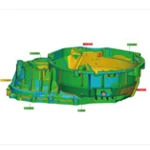
Cooling stable stage
Saddle buckling mode forming:
Four-corner area: continuously displays red, and the cloud image shows an "island-shaped" highlighted area
Center area of the board: dark blue overlay
Transition zone: The red → blue gradient strip extends along the diagonal, forming a typical hyperbolic paraboloid topology.

The XTOP3DD XTDIC 3D full-field strain measurement system enables high-precision full-field deformation measurement—including 2D or 3D displacement and strain fields—and is particularly well-suited for tracking dynamic processes such as vibration, impact, or fatigue testing. Furthermore, its non-contact nature eliminates the interference with specimens often caused by contact-based methods (like traditional strain gauges), making it ideal for soft, high-temperature, or fragile materials.
DIC technology offers extremely high measurement precision, achieving sub-pixel displacement resolution. It demonstrates strong environmental adaptability, allowing for testing in outdoor or extreme conditions. It provides full-field visualization data, intuitively displaying areas of concentrated deformation—such as crack initiation sites—to help researchers quickly pinpoint issues.
However, DIC measurements are subject to certain sources of error, including camera calibration deviations, ambient lighting fluctuations, vibration interference, and inherent algorithmic limitations. Improving accuracy requires optimizing speckle pattern quality, refining calibration methods, and employing advanced image processing algorithms. Ongoing improvements to DIC algorithms have enhanced matching efficiency and precision, while the integration of multiple technologies has expanded its application to multi-physics field measurements.
Compared to traditional strain gauges or laser interferometers, DIC technology holds a distinct advantage in providing full-field data, though it may still need to be combined with other techniques in certain high-frequency or ultra-high-precision scenarios. Looking ahead, DIC will evolve toward real-time capabilities and intelligent operation, while integrating deeply with other measurement methods to meet increasingly complex engineering and scientific research needs.