I. Experimental Background
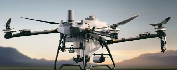
During high-speed rotation (5,000–10,000 RPM), drone rotors are subjected to complex aerodynamic loads and centrifugal forces; their dynamic deformations (such as bending and twisting) directly impact flight performance and structural integrity. Traditional contact sensors (e.g., strain gauges) struggle to capture transient deformation fields under high-speed rotation and may interfere with the airflow. Drone manufacturers urgently require a measurement solution capable of accurately quantifying high-speed dynamic deformation that is also suitable for practical engineering application.
Adverse effects of rotor flapping deformation:
1. Changes in the rotor blade's angle of attack, affecting rotor lift and moments.
2. Rotor blade vibration, impacting the rotor's service life and reliability.
3. Impairment of the rotorcraft's controllability and stability.
II. Principles, Technical Comparison, and Importance of High-Speed DIC
Digital Image Correlation (DIC) is a technique that calculates 2D or 3D coordinates based on single images or image sequences captured by industrial CCD cameras, thereby deriving measurements of displacement, velocity, and acceleration. By analyzing local displacements between these coordinates, strain values and strain rates are calculated. DIC enables full-field measurement of the sample surface with high spatial resolution.
High-Speed Digital Image Correlation (HS-DIC) is a non-contact, full-field measurement method based on optical imaging and computer vision; it is used to capture 3D displacement fields, strain fields, and motion trajectories on object surfaces during high-speed dynamic processes. HS-DIC systems utilize high-speed cameras as sensors, enabling the measurement of strain and displacement during highly dynamic events.
High-Speed DIC vs. Traditional Measurement Techniques
|
Comparison dimensions
|
High-speed DIC
|
Strain gauge/accelerometer
|
|
Measurement range
|
Full-field 3D displacement/strain (millions of measurement points)
|
Single-point/local one-dimensional data (such as uniaxial strain or acceleration)
|
|
Dynamic response
|
Frame rates ranging from 500 Hz to the MHz range; suitable for high-speed transient processes.
|
Bandwidth < 1 kHz; signals are prone to delay or drift.
|
|
Measurement accuracy
|
Displacement accuracy: 0.01 pixels (approximately sub-micron level)
Strain accuracy: 20–50 με
|
Strain gauge accuracy: ±1–10 με (highly dependent on the bonding process)
|
|
Spatial resolution
|
High-density full-field data, with a minimum point cloud spacing of 0.1 mm.
|
Single-point or sparse array (requiring the deployment of multiple sensors)
|
|
Applicable Scenarios
|
Harsh environments such as high temperatures, intense vibration, and high-speed rotation.
|
Susceptible to electromagnetic interference; added mass affects accuracy.
|
Importance of High-Speed DIC Technology Applications
1. Capturing the full-field strain distribution of the rotor from startup to steady-state operation (e.g., centrifugal strain at the root and aeroelastic deformation at the tip);
2. Analyzing blade cross-sectional properties such as torsional, lead-lag, and flapping stiffness;
3. Establishing a quantitative analysis framework for rotor dynamic performance to drive rotor structural iteration and the optimization of flight control algorithms.
III. System Components and Key Specifications
Components of the High-Speed DIC Measurement Solution (Hardware & Software)
High-Speed DIC Measurement System: XTDA software is specifically designed to track the displacement, velocity, acceleration, angle, trajectory, and pose of key target points. It enables the analysis of 3D displacement, deformation, and dynamic trajectories based on the motion of markers and feature points.
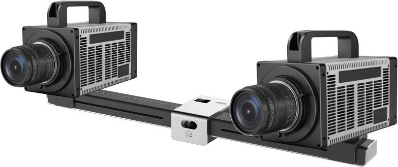
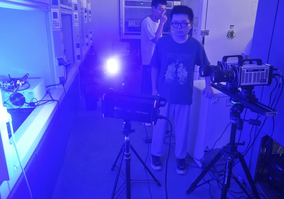
High-Speed Cameras: Two high-speed cameras capable of ultra-high-speed measurement (exceeding 1 million frames per second) with a tracking accuracy of up to 0.01 px and a maximum resolution of 2048 × 1024.
Illumination System: External large-field-of-view stroboscopic light source or high-power continuous light source; blue LED cold light source (to eliminate ambient light interference) providing uniform illumination across the specimen surface.
Key specifications of XTDIC-SPARK technology:
-
Ultra-high-speed measurement exceeding one million frames;
-
Tracking accuracy up to 0.01px;
-
Measurement of 2D/3D coordinates, displacement, deformation, strain, angles, velocity, and acceleration;
-
Simultaneous tracking of massive numbers of targets using feature-based and matching-based tracking algorithms;
-
6DoF trajectory and pose tracking;
-
Support for importing various image or video formats for analysis.
Problems Addressed
Utilizing high-speed Digital Image Correlation (DIC) technology (the XTDIC-SPARK system) enables the precise quantification of strain fields, displacement distributions, and key-point motion trajectories across the entire operational cycle—from startup to stable rotation—providing essential data to support the design and optimization of UAV rotors.
Dynamic Deformation Measurement: Captures the dynamic deformation characteristics of rotors during high-speed rotation.
Design Validation: Validates CFD simulations and design data through dynamic deformation analysis under actual flight loads and complex aerodynamic interference.
Product Optimization: Leverages high-speed DIC technology to establish quantitative data analysis of rotor dynamic performance, driving the iterative design of rotor structures and the optimization of flight control algorithms.
IV. Practical Case Study: Measurement of Deformation Under Load in Drone Rotor Blades
Experimental Analysis Scenarios:
Phase 1 (Startup Phase): Capturing stress concentration at the rotor blade root (deformation analysis);
Phase 2 (Transition Phase): Deformation and periodic vibration induced by tip vortices;
Phase 3 (Steady-State Phase): Quantifying blade surface bending deformation caused by aerodynamic lift.
Practical Case: Data and Analysis
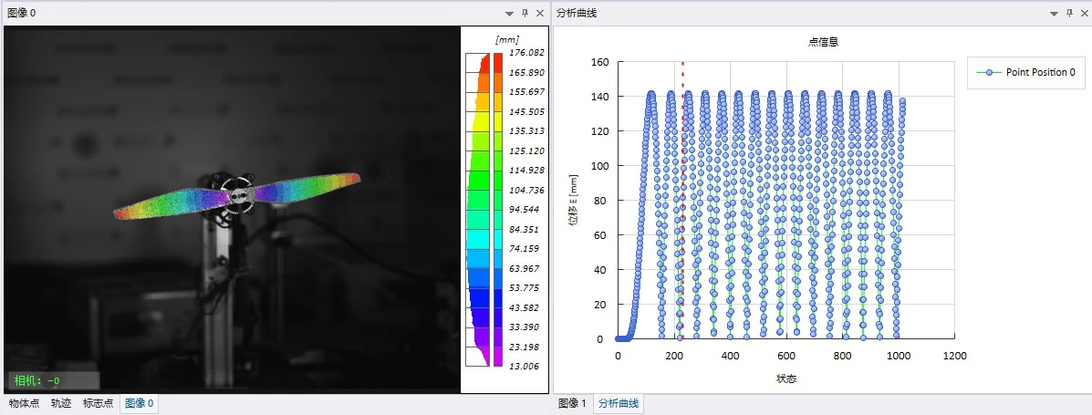
In the XTDA software, a calculation region and seed points are created to determine the 3D coordinates of speckle markers, which are then used to calculate the strain and displacement fields.
Rotor displacement results and key-point displacement analysis curves
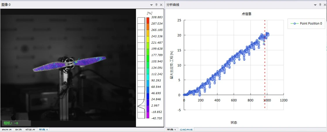
Rotor blade strain results and engineering curves of maximum principal strain at key points.
Practical Case Study: Data Analysis and Conclusions
Analysis of drone rotor deformation—from startup to steady-state operation—yields test data that can be used to optimize structural design, material selection, and dynamic performance, as well as to drive design innovation.
-
Enhance the efficiency of dynamic performance analysis, achieving rotor weight reduction while maintaining flexural strength;
-
Analyze deformation during flight to optimize rotor geometry, thereby improving rigidity and stability;
-
Identify high-stress zones and optimize geometric parameters (such as airfoil thickness and twist angle) to prevent excessive local deformation;
-
Integrate deformation characteristics into control algorithms to enable precise measurement and compensation of rotor flapping motion.