To address the challenge of measuring large-deflection wing deformation on large high-wing aircraft during flight, a multi-camera dynamic Digital Image Correlation (DIC) system was employed to capture dynamic speckle images of the wing. By designing a speckle-matching algorithm capable of handling steep inclination angles and a real-time vibration compensation calibration method, issues related to low image correlation and flight-induced vibration interference were resolved.
Validation conducted on a 1:10 scale wing test rig—using the XTOP3D XTDIC-STROBE 3D dynamic measurement system for synchronous measurement and accuracy comparison—demonstrated a full-field measurement accuracy of 0.21 mm over a 2-meter range. This performance meets the requirements for monitoring wing deflection under flight loads, providing a high-precision, full-field dynamic deformation measurement solution for aircraft aeroelastic analysis.
I. Background
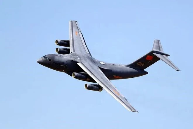
Large aircraft with high-mounted wings are subjected to immense aerodynamic loads during flight; for instance, the wingtips of aircraft with spans of 40–50 meters can oscillate vertically by more than one meter. Given the magnitude of this deformation, it is essential to acquire 3D distribution data regarding wing deformation during flight.
Traditional strain gauge methods (with a measurement point density of ≤20 points/m²) struggle to capture the full-field strain distribution, while photogrammetry is often constrained by vibration and viewing angle limitations. NASA previously employed Digital Image Correlation (DIC) technology during A380 wing testing to measure deformation in specific areas, yet encountered high matching failure rates under conditions involving steep inclination angles (>40°).
By utilizing a distributed camera layout, dynamic calibration compensation algorithms, and real-time vibration compensation calibration methods, precise reconstruction of the full-field deformation under complex motion is achieved, offering valuable guidance for actual aircraft measurements.
II. Challenges and Solutions in Dynamic Wing Measurement
Challenge 1: Low image correlation due to high-angle deformation
During flight, wing deflection angles can reach 40–50°, causing severe tilting of the camera's perspective. This results in drastic deformation of the speckle pattern and distortion of the grayscale distribution; consequently, traditional DIC algorithms suffer from matching failure rates exceeding 30%, leading to discontinuities in the displacement field.
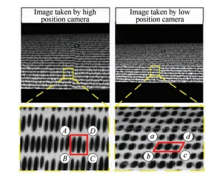
Weakly correlated images of large deformations captured by high-position and low-position cameras.
Technical Solution:
A high-tilt, low-correlation speckle matching method is employed. Reference and target image sequences captured by the cameras serve as the two input sets, with matching operations performed on reference and target subsets within their respective sequences. This approach provides reliable initial values, enabling the linear iterative least-squares algorithm to achieve greater speed, accuracy, and robustness.
Multi-level Hierarchical Matching Algorithm:
Utilizing feature-point-guided progressive matching, this method decomposes large-scale global deformation into a combination of local rigid-body motion and iterative small-deformation analysis.
Multi-camera Viewpoint Fusion:
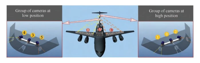
A dual-group camera array configuration—comprising "high" (vertical stabilizer) and "low" (fuselage) positions—is used to achieve a field of view of ±60°. Global pose is optimized via bundle adjustment during calibration, and the four-camera system increases blind-zone coverage from 62% to 98%.
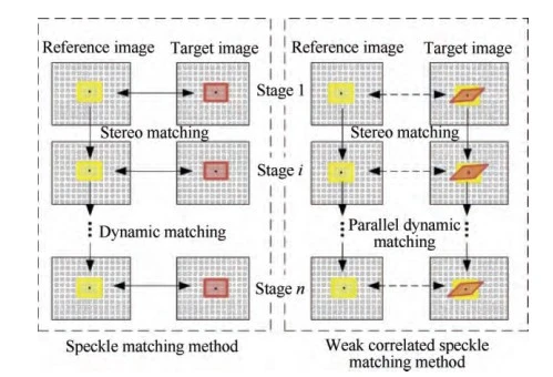
Speckle matching method for high-tilt angles with weak correlation
Challenge 2: Measurement reference drift caused by flight vibration
During actual flight measurements, the aircraft is subjected to high-speed airflow, causing vibration in the vertical stabilizer section where the measurement cameras are mounted; consequently, real-time dynamic correction of the cameras' position and orientation is required.
Technical Solutions:
Dynamic Camera Correction
Using the dorsal section of the aircraft as a rigid, stationary reference, the position and orientation of the reference camera within the world coordinate system—specifically, the camera's exterior orientation parameters—are calculated in real time.
By utilizing pre-calibrated relative exterior parameters, the absolute exterior parameters for the paired measurement camera are calculated for each image frame, thereby achieving dynamic correction of the measurement camera.
Camera Vibration Compensation
During calibration, the interior orientation parameters of all cameras are determined, establishing known relative positional relationships between them. Given the exterior parameters of any single camera, the absolute exterior parameters of its paired camera can be derived using the known relative exterior parameters.
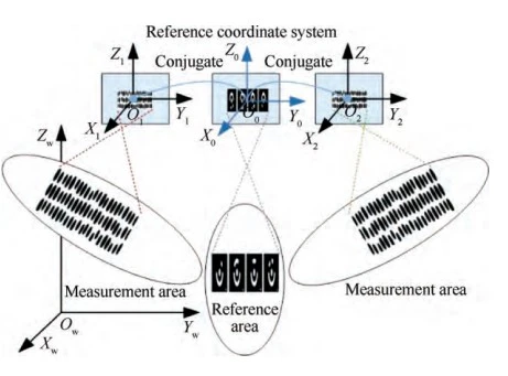
Diagram of camera vibration compensation
III. 3D Full-Field Dynamic Deformation Measurement of the Wing
A measurement scheme for the 3D full-field deformation of the wing is designed, taking into account the structural characteristics of high-wing aircraft.
Camera Installation Plan
Measurement Process and Results
Following the separate calibration of internal and external parameters, image acquisition of the wing deformation commenced. During this process, the camera's position was calculated in real-time based on the 3D coordinates of fixed points on the upper wing surface, followed by the computation of full-field wing deformation data.
The XTOP3D XTDIC-STROBE system was employed to verify the measurement accuracy of this study; the accuracy of the full-field deformation analysis was validated by comparing it with the synchronously calculated 3D coordinates of key points. This system achieves a measurement accuracy of 0.01 mm over a 300 mm × 400 mm field of view, and the obtained results serve to evaluate the accuracy of the full-field wing deformation measurement.
IV. Verification of the Flight Test Scheme
A simulation test environment was established using a 1:10 scale aircraft model as the measurement object to verify the feasibility and effectiveness of the measurement scheme.
To evaluate measurement accuracy, the XTOP3D XTDIC-STROBE system was used to simultaneously track markers on the wing surface, and the accuracy of the scheme was validated through a comparative analysis of the dynamic 3D coordinates of these markers.
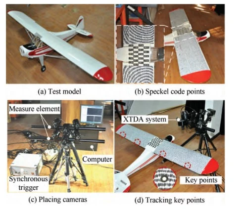
Wing deformation measurement test platform
Simulated Measurement Results
Images were acquired synchronously using a six-camera probe setup and two XTDIC-STROBE systems. Subsequently, full-field deformation analysis was performed to obtain the full-field displacement and deformation results for the wing.
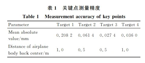
The displacement results for four key points—measured by the proposed setup and the XTDIC-STROBE systems—were compared. By analyzing the mean absolute difference, the accuracy of the wing's full-field deformation measurement system was determined; the displacement measurement error was found to be less than 0.21 mm over a 2-meter span.
Measurement accuracy of key points
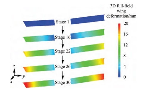
The color-coded contour maps of the 3D displacement fields representing wing deformation under different imaging conditions are shown in the figure:
3D full-field wing deformation colormap
V. Analysis Conclusions
A scheme for measuring the 3D full-field wing deformation of a high-wing aircraft during actual flight was proposed; a dedicated measurement system was developed and subjected to simulated measurements; and synchronous measurements and accuracy comparisons were conducted using the XTDIC-STROBE 3D dynamic deformation measurement system (by Xintuo 3D), with error results analyzed via charts.
1) The displacement measurement error for the test wing was less than 0.21 mm/2 m.
2) Simulated measurement results demonstrated that the described DIC measurement scheme is effective and feasible.
This study provides a valuable reference for the practical engineering measurement of wing deformation in high-wing aircraft during flight.
Case excerpted from: [Wei Bin, Liang Jin, Ren Maodong; State Key Laboratory for Manufacturing Systems Engineering, School of Mechanical Engineering, Xi'an Jiaotong University; "Scheme for 3D Full-Field Wing Deformation Measurement of Large High-Wing Aircraft"]