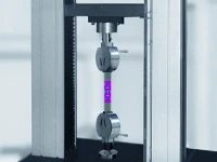
As a non-contact, full-field, and high-precision optical measurement technique, the high-speed Digital Image Correlation (DIC) system offers unique advantages for the modal measurement and analysis of printed circuit boards (PCBs). Compared to traditional methods using accelerometers or laser vibrometers, DIC technology eliminates the influence of added mass, enables high-density full-field measurement, and intuitively captures complex mode shapes, making it particularly suitable for characterizing the dynamic properties of lightweight, thin PCBs.
This paper presents a systematic analysis of the application and practical case studies of XTOP3D high-speed DIC technology in vibration measurement and modal analysis, providing a reliable basis for enhancing the operational reliability and service life of PCBs.
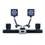
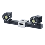
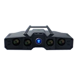
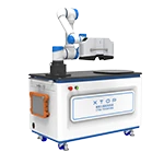
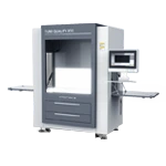
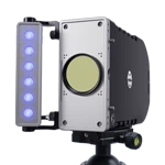
 Measurement System")
1. Technical Background and Requirements
Modal analysis of PCBs is crucial in the design of electronic products for vibration resistance and reliability. It is used to determine the circuit board's natural frequencies and mode shapes, thereby predicting whether resonance will occur under dynamic loads—potentially leading to solder joint failure, component cracking, or signal anomalies. By identifying parameters such as natural frequencies, mode shapes, and damping ratios, modal analysis provides a quantitative engineering basis for optimizing PCB vibration design, enhancing rigidity, or avoiding external excitation frequencies.
Traditional PCB modal testing methods primarily rely on accelerometers, strain gauges, and laser Doppler vibrometers (LDV), yet these methods suffer from significant limitations.
The added mass of accelerometers can alter the dynamic characteristics of lightweight PCBs, resulting in frequency shifts and changes in damping; single-point measurement techniques struggle to capture the full-field mode shape distribution; and laser scanning methods require long testing times and are sensitive to environmental conditions.
2. Value of Introducing DIC Technology
Digital Image Correlation (DIC) modal analysis utilizes DIC technology to perform non-contact measurements of structural images during vibration. By determining parameters such as natural frequencies and damping ratios, it helps prevent resonance and enhances structural performance under dynamic loads.
High-speed DIC systems combine DIC algorithms with high-speed imaging technology, enabling the capture of structural dynamic responses on millisecond or even microsecond timescales and providing a novel technical approach to vibration measurement and modal analysis.
The XTOP3D XTDIC-SPARK 3D high-speed measurement system features built-in ODS (Operating Deflection Shape) modal analysis capabilities. Utilizing high-speed cameras to capture high-frequency vibrations, the system offers a streamlined testing process, efficient data processing, and accurate modal identification and mode shape measurement. It can clearly distinguish between closely spaced modes and local modes, precisely identify vulnerable areas on plates, and validate the accuracy of simulation models.
3. Analysis Targets for High-Speed DIC Technology
-
Acquisition of dynamic characteristic parameters: Precisely determine the first three natural frequencies and their corresponding mode shapes of the PCB under impact loading.
-
Identifying resonance risks: Use modal analysis results to pinpoint the PCB's sensitive frequency ranges, providing a direct basis for assessing the likelihood of resonance.
-
Pinpointing mechanical weak points: Visually analyze vibration modes of various orders to identify regions exhibiting maximum displacement or concentrated strain energy—areas that represent potential risks for weld fatigue and component damage.
-
Establish an optimization baseline: Provide a quantifiable reference for subsequent design improvements (such as adding supports, altering mounting points, or adjusting layout) to increase the PCB's fundamental natural frequency and avoid critical excitation frequency bands.
 measurement system analyzes the frequency of circuit board impact vibration.")
4. Practical Case Study of High-Speed DIC Modal Analysis
Excitation Methods for DIC Modal Testing
Impact excitation: An impact hammer is used to strike the PCB, generating transient excitation at the natural frequencies of the third-order modes (198 Hz, 289 Hz, and 453 Hz) and eliciting a broadband frequency response.
Data Acquisition and Processing Workflow
The circuit board was excited via hammer impact, and the high-speed camera integrated into the XTOP3D XTDIC-SPARK 3D high-speed measurement system captured the response at a frame rate of 10,000 fps and a resolution of 1280x864.
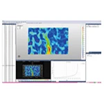
High-speed camera image acquisition of the PCB's vibration response was triggered synchronously. The ODS (Operating Deflection Shape) function within the XTOP3D DIC software was utilized for modal analysis, yielding the frequency curves and modal analysis results shown below.
Frequency curve results for the PCB under impact excitation:
 measurement system analyzes the frequency of circuit board impact vibration.")
Frequency 1–198 Hz
 measurement system analyzes the frequency of circuit board impact vibration.")
Frequency 2–289 Hz
 measurement system analyzes the frequency of circuit board impact vibration.")
Frequency 3–453 Hz
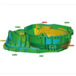
Using the Xintuo 3D DIC modal analysis module, the modal analysis results are output as follows:
First-order modal analysis
Critical Weak Areas: Regarding the first-order bending mode (198 Hz), the peak vibration displacement occurs at the board-to-foot connector; adding local stiffeners at the location of maximum displacement could be considered.
 measurement system analyzes circuit board vibration mode results.")
Modal analysis at 198 Hz (5000 frames)
Second-order modal analysis
Regarding the second-order bending mode (289 Hz), the region of peak vibration displacement is located at the support edge; this value can be optimized through edge reinforcement design.
 measurement system analyzes circuit board vibration mode results.")
Modal analysis at 289 Hz (5,000 frames)
Third-order modal analysis
To address the third-order bending mode (453 Hz), avoid a lack of support for pins located at the PCB edges; ensure that the housing or framework provides support beneath them.
 measurement system")
Modal analysis at 453 Hz (5,000 frames)
5. Experimental Conclusions
Experimental validation demonstrates that combining high-speed Digital Image Correlation (DIC) technology with the impact hammer method enables accurate measurement of circuit board vibration. The DIC modal analysis module allows for the extraction of multi-order modal parameters, facilitating rapid, accurate, and non-contact measurement while eliminating the added mass effect associated with accelerometer-based testing.
Under impact excitation, modal analysis clearly reveals vibration displacement variations at component corner pins, identifies locations of peak pin stress, and highlights critical pins prone to cracking. These test results support comprehensive optimization at both the board level (e.g., increasing PCB thickness, adding constraints, or repositioning components) and the pin level (e.g., modifying lead routing, increasing pin bend angles, or enlarging cross-sectional areas), thereby providing a valuable reference for enhancing PCB reliability.
Overall, high-speed DIC technology holds significant promise for PCB vibration testing and modal analysis, positioning it as a key tool for the reliability testing and design optimization of electronic products.