Full-field deformation measurement of large-scale structures is a recognized technical challenge in the field of engineering testing. From bridge health monitoring to aircraft fuselage strength testing, from ship structural analysis to wind turbine blade testing, these applications place stringent demands on the field of view, spatial resolution, and measurement accuracy of DIC measurement systems. Traditional measurement methods often fall short in meeting these challenges, while the emergence of multi-camera DIC technology provides a practical and feasible technical solution for solving the problem of large-scale full-field-of-view measurement.
The core challenges of large-size measurement
The contradiction between field of view and resolution
The fundamental principles of optical measurement dictate the constraint between field of view size and spatial resolution. Increasing the field of view means increasing the physical size corresponding to a unit pixel, which in turn reduces resolution. When the size of the object being measured reaches the meter or even ten-meter level, the primary challenge becomes how to cover the entire field of view while ensuring sufficient spatial resolution.
Environmental conditions are difficult to control
Large structures are often impossible to measure in a precision laboratory environment. Environmental vibrations, airflow disturbances, temperature gradients, and changes in lighting can all affect measurement accuracy. These adverse factors are even more difficult to control, especially in outdoor field testing.
Measurement synchronization requirements
Deformation measurements of large structures typically involve simultaneous recording at multiple measurement points. Any time-delayed synchronization will introduce artifacts into the measurement results, affecting the interpretation of the true deformation field.
Difficulty in establishing a benchmark reference
DIC measurements require the initial state before deformation as a reference. For large-sized structures, establishing a stable and reliable geometric reference and ensuring coordinate consistency across the entire measurement field is a crucial aspect of the technical implementation.
Multi-camera DIC system architecture
Distributed acquisition architecture
To address the needs of large-size measurements, the multi-camera DIC system adopts a distributed acquisition architecture:
The main acquisition control unit is responsible for uniformly controlling the acquisition timing of all cameras, ensuring microsecond-level synchronization accuracy.
Edge computing nodes : Deployed near the measurement area, they perform image preprocessing and data caching locally, reducing data transmission pressure.
High-speed communication network : Employing gigabit Ethernet or fiber optic networks to achieve high-speed transmission of massive image data.
Central processing server : responsible for data fusion, 3D reconstruction, and post-processing analysis.
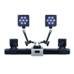
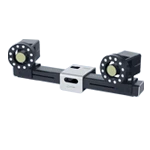
Modular camera configuration
The system adopts a modular camera configuration scheme, which can be flexibly adjusted according to measurement requirements:
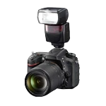
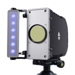
Measurement camera : A high-resolution industrial camera responsible for acquiring deformed images.
Reference camera : Low-resolution wide-angle camera, used for global positioning and coordinate transfer.
Lighting unit : Controllable LED light source or strobe light source to ensure uniform and stable illumination.
Mechanical support : A high-precision gimbal and tripod system ensures camera position stability.
Strategies for Measurement
Large-size measurements employ a layered measurement strategy, analyzing the data layer by layer from macroscopic to microscopic:
1. Global Monitoring Layer : Uses a wide-angle camera array to acquire the overall deformation trend of the structure.
2. Detailed Regional Measurement Layer : Deploy high-resolution cameras in key areas to acquire detailed local deformation data.
3. Focused Layer : Ultra-high resolution local magnification measurement is used in areas of concentrated strain.
The three layers of data corroborate each other and are refined step by step, enabling a comprehensive and accurate understanding of the deformation of large-sized structures.
Key implementation technologies
Camera layout optimization design
Camera layout design is a crucial factor determining the success or failure of a measurement. We use professional layout optimization software, taking into account the following factors:
- Coverage integrity : Ensure no blind spots or omissions in the measurement area.
- Reasonable overlap : Maintain sufficient overlap between adjacent cameras (recommended greater than 30%) to facilitate data stitching.
-Optimal viewing angle : Each measurement point is observed simultaneously by at least two cameras (satisfying stereo matching requirements).
- Uniform lighting : Avoid strong glare and shadow areas.
High-precision calibration technology
The calibration of large-size DIC measurements adopts a hierarchical calibration strategy:
1. Single-camera calibration : Accurately calibrate the intrinsic parameters and distortion coefficients of each camera under laboratory conditions.
2. Relative position calibration : High-precision calibration targets are set up at the measurement site to calibrate the relative positional relationships between each camera.
3. Global coordinate binding : Precisely linking the measured coordinates with the engineering coordinate system using control points.
4. Dynamic compensation : Real-time monitoring and dynamic compensation of camera position changes during measurement.
Image enhancement and preprocessing
To address image quality issues in large-scale field measurements, the system employs multi-level image enhancement techniques:
Noise suppression : A joint spatiotemporal filtering algorithm is employed to effectively reduce image noise while preserving edge details.
Contrast Enhancement : Adaptive histogram equalization improves image quality in areas of uneven lighting.
Distortion correction : Real-time distortion correction based on calibration parameters to ensure geometric measurement accuracy.
Motion blur compensation : Reducing image degradation caused by vibration and motion through image deblurring algorithms.
Full-field data fusion
The fusion of multi-camera data employs a global optimization method based on feature points:
- Extract and match feature points between adjacent image pairs
- Establish a bundle adjustment model to uniformly optimize all observation data.
- Iterate until the global error is minimized.
- Generate seamlessly stitched full-field measurement results
Best practices for field testing
Test preparation phase
1. Site survey : Thoroughly understand the measurement environment, site conditions, and characteristics of the structure being measured.
2. Scheme Design : Develop detailed surveying plans and emergency response plans based on the survey results.
3. Equipment Pre-inspection : Perform functional tests and accuracy calibrations on all equipment before departure.
4. Speckle pattern preparation : Select a suitable speckle pattern preparation method to ensure that the speckle quality meets the requirements.
Test Implementation Phase
1. Environmental monitoring : Continuously monitor environmental parameters such as temperature, humidity, and vibration.
2. System Calibration : Perform a complete system calibration under field conditions.
3. Preload Acquisition : Acquire initial reference images after applying preload.
4. Formal Measurement : Execute the measurement task according to the predetermined plan and record all raw data.
5. Quality monitoring : Real-time monitoring of data quality; timely retesting if problems are found.
Data processing stage
1. Data integrity check : Confirm that all expected data has been fully collected.
2. Image quality assessment : Each frame of the image is scored for quality, and problem areas are marked.
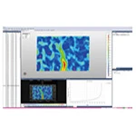
3. Calculation and Processing : Perform DIC calculations to generate displacement and strain fields.
4. Result Verification : Compare and verify the results with theoretical expectations and historical data.
5. Report Generation : Compile and analyze the results, and write a technical report.
Typical application areas
civil Engineering
Bridge load testing and health monitoring
Deformation analysis of large building structures
- Monitoring of tunnel shield construction process
Aerospace
- Static test of the entire aircraft fuselage
- Deformation measurement of rocket fuel tanks
- Satellite deployment mechanism motion trajectory monitoring
Shipbuilding and Ocean
- Hull structural strength test
- Wave load response of offshore platforms
Submarine pressure hull deformation test
New energy
- Wind turbine blade load test
- Reliability verification of photovoltaic support structure
- Hydrogen storage tank pressure cycle test
Large-scale full-field-of-view measurement is an important application area for multi-camera DIC technology and the scenario in which its technological advantages are best demonstrated. Through reasonable system configuration, standardized implementation procedures, and a professional technical team, various challenges in large-scale measurement can be effectively overcome, resulting in reliable and accurate measurement results.
As a leading provider of optical measurement solutions in China, we have successfully completed large-scale DIC measurement projects for numerous clients, accumulating rich practical experience. Whether your measurement object is a bridge, building, or aircraft, we can provide you with customized technical solutions and full-process technical support.