Digital image correlation (DIC) technology, as a mainstay of modern optical non-contact full-field deformation measurement, has profoundly transformed many fields such as materials testing, structural analysis, and industrial inspection. In the development of DIC technology, 3D-DIC measurement systems have rapidly gained popularity and established their mainstream position. So, what key factors have driven the rise of 3D-DIC and made it the industry's preferred choice?
I. Beyond the limitations of the plane
The deformation of objects in the real world is inherently three-dimensional. When most engineering structures and materials are subjected to force, heat, or other physicochemical changes, they not only undergo displacement and strain in the plane (X, Y directions), but also inevitably produce out-of-plane displacement (Z direction) and corresponding out-of-plane strain components. This three-dimensional deformation characteristic is an objective physical law that is independent of measurement methods.
Commonly existing out-of-plane displacement:
Bending/Torsion: Beams, plates, and shells will inevitably undergo bending deformation under load, resulting in significant out-of-plane displacement (W).
Buckling/Instability: When a thin-walled structure buckles under compressive load, out-of-plane displacement is its main deformation characteristic.
Complex loads: Asymmetric loads, impact loads, thermal loads, etc., can easily induce three-dimensional spatial deformation.
Material anisotropy/nonhomogeneity: such as composite materials and biological tissues, whose internal structure causes deformation to naturally have three-dimensional properties.
Geometric shape: Curved surfaces and irregular shapes, whose deformation paths naturally exist in three-dimensional space.
Fatal errors caused by out-of-plane displacement:
When there is a non-negligible out-of-plane displacement (W), the measurement principle of 2D-DIC can lead to serious systematic errors:
Perspective error: When an object moves along the optical axis (Z direction), its projected position on the camera's imaging plane changes. The 2D-DIC algorithm misinterprets this projected displacement as an in-plane displacement (U, V). Even if the object itself does not move in the XY plane, any out-of-plane motion will be "seen" as a false in-plane displacement by 2D-DIC.
Error amplification effect: The magnitude of perspective error is directly proportional to the displacement from the surface (W) and inversely proportional to the object distance (Z). This means that when measuring at close range or when there is significant displacement from the surface (such as vibration or impact), the measurement results of 2D-DIC may be completely distorted and lose their engineering reference value.
Strain calculation distortion: The in-plane strain field (εxx, εyy, εxy) calculated from an incorrect in-plane displacement field naturally contains significant errors. It fails to capture the key strain components (εzz, εxz, εyz) associated with out-of-plane displacement, which are often crucial in failure analysis and fatigue life prediction.
II. Capturing Realistic Deformation from All Angles
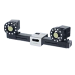
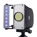
The 3D-DIC system uses two or more precisely calibrated cameras to simultaneously capture speckle images of the surface of the object under test from different angles. Through stereo vision principles and sophisticated image matching algorithms, the system can reconstruct the three-dimensional spatial coordinates of points on the object's surface and accurately calculate its three-dimensional displacement field (U, V, W) and full-field three-dimensional strain tensor before and after deformation. This capability brings revolutionary advantages:
Measuring true 3D deformation:
Core Value: This is the most fundamental advantage of 3D-DIC. It can directly and completely measure the displacement of an object in any direction in space (including the crucial out-of-plane displacement W) and all strain components (εxx, εyy, εzz, εxy, εxz, εyz), without assuming a planar deformation state. This provides the most realistic and comprehensive understanding of the mechanical behavior of materials or structures.
Application scenarios: Almost all tests involving non-planar, complex shapes, or significant out-of-plane motion.
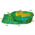
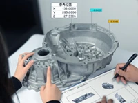
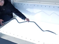
Deformation analysis of complex curved surface parts: such as the deformation and springback of automotive body panels, aircraft skins, injection molded parts, and sheet metal parts under load.
Three-dimensional volumetric strain measurement (approximate): By combining object shape information, strain in the thickness direction can be evaluated, which is especially suitable for thin-walled but not absolutely planar structures.
Buckling and instability studies: Accurately capture the three-dimensional deformation modes and critical loads when a structure becomes unstable.
Vibration analysis (full mode): Obtain the vibration displacement and mode shape (in-plane + out-of-plane) of the structure in any direction in space.
Impact collision test: Comprehensive analysis of the complex three-dimensional deformation process of the structure during the collision.
Biomechanics (e.g., joint motion, soft tissue deformation): Analyzing the complex three-dimensional motion of living or ex vivo tissues.
Eliminate out-of-plane motion error:
Addressing the pain point: The biggest limitation of 2D-DIC is its extreme sensitivity to out-of-plane displacement; even minute out-of-plane movements can introduce significant in-plane displacement measurement errors (perspective errors). 3D-DIC fundamentally eliminates this source of error because it directly measures three-dimensional position without relying on planar assumptions.
Application scenarios: Any situation where unavoidable surface movement or unevenness of the measured surface may exist, such as:
The specimen may be slightly twisted or bent during the test.
The surface being measured has an initial curvature or roughness.
The complex motion trajectory of the specimen during high-speed testing.
Higher measurement accuracy and reliability (in applicable scenarios):
Technical Foundation: Multi-view images provide redundant information. Combined with rigorous camera calibration and robust stereo matching algorithms, 3D-DIC typically achieves higher absolute accuracy than 2D-DIC when subjected to out-of-plane interference, especially in measuring spatial coordinates and three-dimensional displacement. Advanced calibration methods and algorithms continue to drive accuracy improvements.
Improved reliability: It is more robust to complex lighting, changes in viewing angle, and partial occlusion (in areas that can be seen by both eyes).
Wider applicability:
Shape insensitive: no longer limited to planar or near-planar objects, it can measure surface deformation of arbitrarily complex shapes.
More flexible perspective: The camera setup is more flexible (although it still needs to meet the requirements of stereoscopic perspective) and is easier to adapt to different testing environments and space constraints.
III. Technological Maturity and Cost Reduction
In addition to its inherent advantages, the maturity of external factors has also greatly promoted the popularization of 3D-DIC:
Improved hardware performance and reduced costs:
High-performance, cost-effective cameras: The performance of high-resolution, high-frame-rate CMOS cameras has improved rapidly while their prices have continued to fall, significantly lowering the barrier to entry for building high-performance 3D-DIC systems.
Leap in computing power: GPU parallel computing and algorithm optimization have significantly reduced the time required to process massive amounts of 3D data, making fast and even near real-time analysis possible.
Mature synchronization and calibration technologies: Reliable hardware synchronization triggering devices and efficient, automated multi-camera calibration tools (such as dedicated calibration boards and self-calibration algorithms) simplify system setup and maintenance.
Software intelligence and ease of use enhancement:
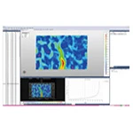
User-friendly interface: DIC business software offers a more intuitive user interface, streamlined workflows, and a wealth of visualization tools, reducing the learning curve for users.
Automation and intelligence: Automatic speckle generation and evaluation, automatic calibration, automatic data processing chain, intelligent result post-processing and report generation functions greatly improve efficiency.
Improved algorithm robustness: More advanced image matching, subpixel algorithms, and error compensation techniques enhance measurement stability and accuracy under complex conditions.