In sectors such as automotive engineering, transportation, packaging, and various military and civilian applications, engineering materials are often subjected to impact loading—such as high-speed collisions or explosions. Understanding the mechanical response of materials under these conditions is essential for their engineering design and application.
A material's mechanical behavior under dynamic loading differs from its behavior under static loading. Conducting dynamic experiments at high strain rates remains a significant challenge compared to quasi-static testing. The Hopkinson tensile test serves as an excellent dynamic testing method for effectively and accurately obtaining strain-rate-dependent stress-strain curves.
Material Testing Requirements for DIC Analysis Systems
Conventional static tensile testing examines materials in a state of static equilibrium, operating on the premise that inertial effects can be ignored. In contrast, explosive or impact loading is characterized by extremely short durations; under these conditions, the material undergoes a dynamic process involving rapid changes over time.
The Hopkinson bar tensile test enables the measurement of stress-strain curves for materials subjected to high strain rates (10²–10⁴/s). Intense impact loads involve significant fluctuations over very short timescales—implying high loading or strain rates—and the resulting stress-strain curves are crucial for investigating the dynamic mechanical properties of the material specimens.
To determine the dynamic mechanical properties of a novel material under dynamic loading, a research institute specializing in material development and engineering mechanics applications conducted high-strain-rate dynamic tensile tests. These experiments utilized the Hopkinson bar tensile testing method, supported by a DIC analysis system and software from Xintuo 3D.
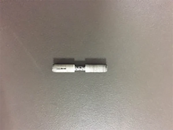
Image: Material samples from the institute.
Regarding the Hopkinson Bar Experiment
This study employs a Hopkinson bar apparatus to test the dynamic mechanical properties of materials within a strain rate range of 10²–10⁴ s⁻¹. The fundamental principle is as follows: when the striker bar (projectile) is launched from the gun barrel at a specific velocity and impacts the input bar, an incident pulse is generated within the input bar; the stress wave travels through the elastic input bar to the specimen, causing the specimen to undergo high-speed deformation under the action of the stress pulse.
As the stress wave passes through the specimen, it generates a reflected pulse that travels back into the elastic input bar and a transmitted pulse that enters the output bar. A velocity measuring device captures the impact velocity of the projectile, while strain gauges bonded to the elastic bars record the strain pulses, enabling the calculation of the material's dynamic stress and strain parameters.

图:实验原理图
DIC Non-Contact Measurement and Inspection Solution
To meet the experimental measurement requirements of the research institute's DIC analysis system, XTOP3D technical engineers utilized two high-speed cameras (megapixel resolution, 16,000 fps). For the experiment, the resolution was set to 768×96, the acquisition rate to 100,000 fps, and 24–70mm lenses were selected.
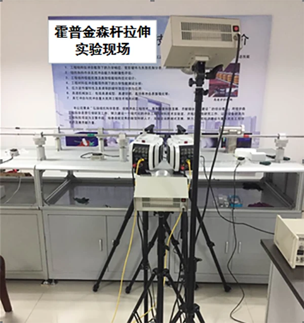
Figure: Hopkinson bar tensile test setup.
DIC Non-Contact Measurement and Inspection Process
The DIC non-contact measurement and inspection process includes: specimen preparation, positioning the specimen, and adjusting camera and lens parameters.
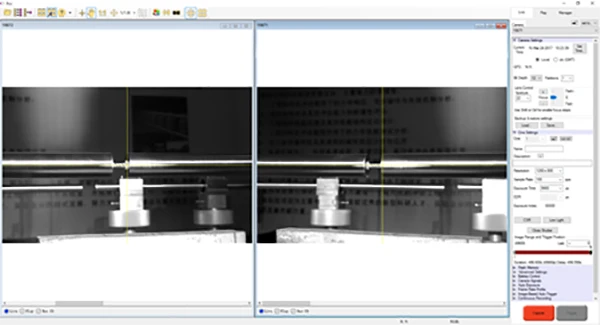
Figure: Adjusting the focal length
Calibration was performed using a 128x96 calibration target at full resolution (1280x800), yielding a deviation of 0.02. The experiment was then conducted with the camera resolution adjusted to 768x96.
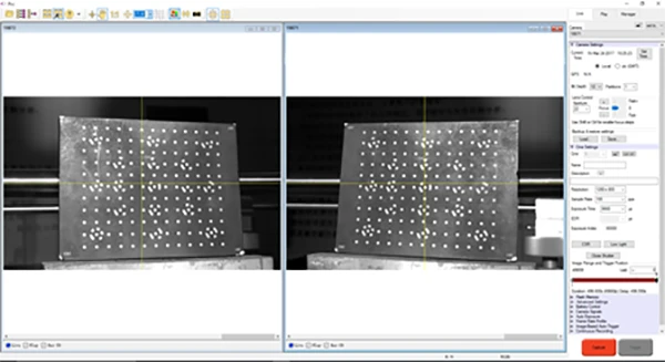
Figure: Camera calibration
After the experiment is completed, post-triggering is used to collect data, and then the XTDIC system software calculates the data.
Analysis of Experimental Data from DIC Non-Contact Measurement
Data Requirements:
1. Select three points (left, center, and right) on the material specimen; plot the curves for true principal strain, engineering principal strain, and secondary strain; and calculate the strain rates.
2. Plot the principal strain and secondary strain curves along a straight line.
3. Generate contour maps for shear displacement and strain.
The material exhibits a maximum strain of approximately 60% and a maximum strain rate of around 1800 s⁻¹. Since the projectile velocity during the experiment is controlled by gas tank pressure, initial velocity variations are inevitable. Consequently, applying different gas pressures results in varying outcomes: sometimes the specimen fractures in a single attempt, sometimes it requires multiple attempts, and at other times, it does not fracture at all.
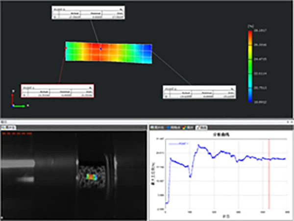

Figure: Strain field and displacement field
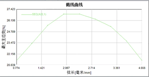
Figure: Strain distribution along the axial cross-section line.
Summary of Material Testing Using the DIC Analysis System
Numerical simulation plays a vital role in engineering design; however, a prerequisite for such simulation is the establishment of accurate stress-strain curves for materials across various strain rates.
By employing the Hopkinson bar tensile test, the research institute successfully obtained stress-strain curves for material specimens during dynamic tensile loading. These data facilitate numerical simulation and support the engineering application and design of the materials.





















