I. Application Background and Detection Requirements
Sheet metal bent mounting brackets serve as fundamental connecting components in equipment manufacturing; the precision of their bend angles, reference spacings, and mounting dimensions directly impacts assembly efficiency, structural integrity, and long-term operational stability.
Due to the complex geometry of these components—characterized by multiple bends and surfaces oriented in different planes—traditional inspection methods suffer from low efficiency, significant blind spots, and difficulty in quantifying springback deviations, failing to meet the requirements for quality control and process optimization. The XTOM blue-light 3D scanner from Xintuo 3D offers an efficient technological solution to address these challenges.
These brackets feature multiple vertical bent surfaces and mounting reference planes, with key quality control parameters covering bend angles, spacing between bent edges, dimensions across different planes, and flatness. Excessive dimensional deviations can lead to issues such as assembly interference, misalignment, and structural stress concentration, making these components a critical focus for quality control in the sheet metal bending process.
II. XTOM Blue-Light 3D Scanning and Inspection Solution
Traditional inspection methods struggle to quantify springback in bent sheet metal brackets; they suffer from blind spots in spatial measurements, mismatched inspection efficiency, and data that fails to guide optimization or pinpoint the root causes of deviations, thereby offering no data-driven support for optimizing bending processes or tooling parameters.
By utilizing the XTOM blue-light 3D scanner, complete 3D morphological data of the bent bracket is rapidly captured. This data is then compared against the CAD design model using specialized inspection software, enabling comprehensive quantitative analysis of bending angles, linear dimensions, and geometric tolerances.
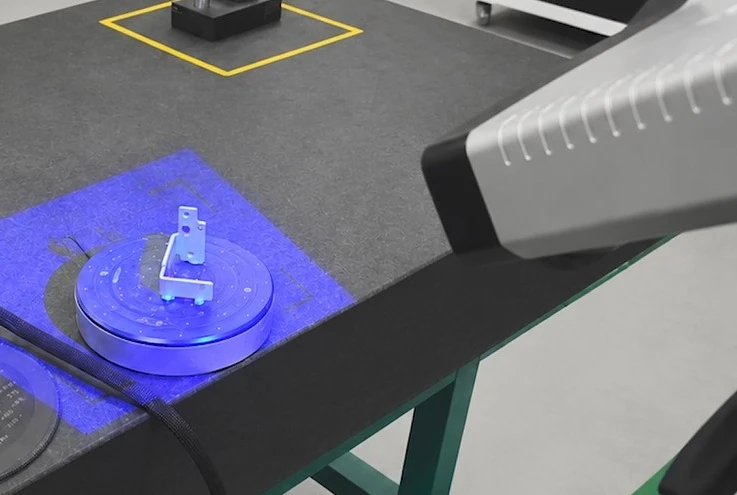
The 3D scanning and inspection process is as follows:
Workpiece Pre-treatment
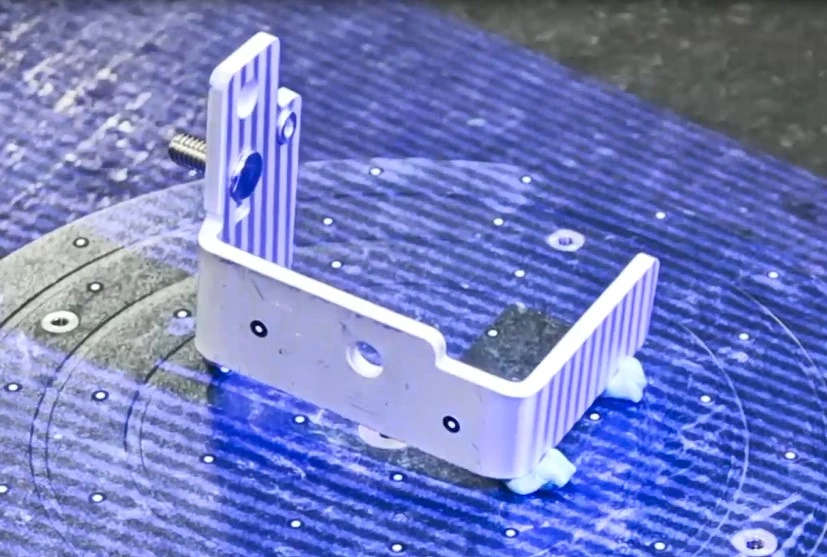
A thin layer of matte imaging spray is applied to the sheet metal surface to eliminate reflective interference; positioning markers are affixed to non-functional areas of the workpiece to provide a high-precision alignment reference for multi-angle scan data.
Full-Field 3D Data Acquisition
The XTOM blue-light 3D scanner rapidly captures the full-field 3D point cloud of the workpiece. Through automatic alignment of multi-angle captures, it faithfully reproduces the intricate features of all bent surfaces, corner transitions, and mounting reference planes, ensuring no data blind spots.
Digital Model Alignment and Inspection Analysis
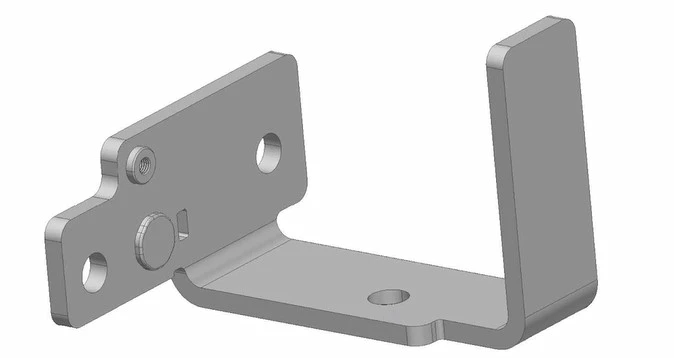
The optimized point cloud data is imported into 3D inspection software and aligned with the product's CAD design model based on datums. This enables automated full-field deviation analysis, bend angle calculation, key dimension annotation, and geometric dimensioning and tolerancing (GD&T) evaluation.
Standardized Report Generation
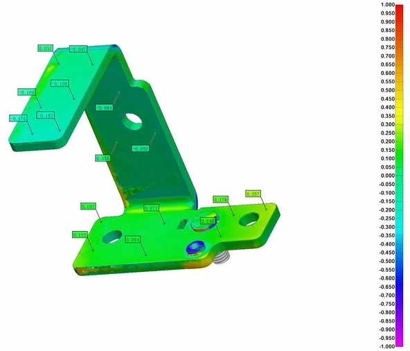
The system generates color-coded deviation maps and dimensional deviation data tables, allowing for the one-click export of standardized inspection reports. All inspection data can be digitally archived, supporting quality traceability and batch-to-batch comparative analysis.
III. Analysis of Inspection Results
By precisely comparing the scanned point cloud with the CAD model, all dimensional deviations of the workpiece are comprehensively quantified. Key inspection results are as follows:
1. Visualization of Global Deviations
The color-coded deviation map provides an intuitive view of the workpiece's overall dimensional distribution. Deviations are relatively pronounced in areas affected by bending springback; this allows for the rapid identification of regions with concentrated deviations and specific out-of-tolerance locations, replacing traditional point-by-point inspection methods.
2. Precise Measurement of Bending Angle
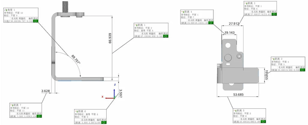
For a nominal bending angle of 90°, the measured angle was 89.757° with a deviation of -0.243°; this allows for the precise quantification of sheet metal springback, providing accurate data to directly guide the adjustment of process parameters.
3. Critical Linear Dimension Deviations
Deviation in bend-to-bend spacing: -0.161 mm; deviation in Z-axis distance from the datum plane: +0.097 mm; deviation in lateral mounting position dimensions: +0.185 mm; deviation in formed bend edge distance: +0.412 mm.
All dimensions can be automatically extracted and evaluated in batches, ensuring data consistency far superior to manual measurement; notably, the positive deviation in the formed bend edge distance aligns closely with bending springback characteristics, intuitively reflecting the patterns of process-induced deformation.
4. Evaluation of Geometric Tolerances for the Reference Surface
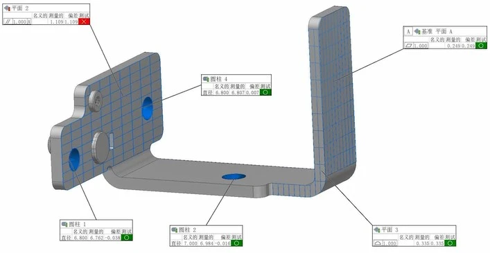
The flatness of the workpiece's mounting interface and its parallelism relative to the reference datum are both within permissible process limits, with no significant warping or deformation. Analyzing the tightness of the fit between the bracket and the mounting base helps prevent issues such as uneven load distribution, loose connections, and stress concentrations after installation, thereby ensuring assembly precision and structural stability.
IV. Application Value
Precise quantification of bending springback: Directly outputs angular deviation and deformation distribution, providing accurate data for adjusting bending parameters and shortening the prototyping cycle for new products.
Comprehensive dimensional coverage: Captures complete 3D data in a single scan—covering all bent surfaces, mounting points, and transition zones—thereby eliminating traditional measurement blind spots and preventing assembly issues.
Efficient quality control for mass production: High-speed optical 3D scanning enables efficient full-dimension inspection, supporting rapid in-line checks and first-article inspection.
Non-contact, non-destructive testing: Purely optical, contact-free measurement prevents surface scratches; suitable for sheet metal parts with various surface finishes and applicable to inspection across the entire production process, from semi-finished to finished goods.
Digital process control: Inspection data can be permanently archived, supporting batch trend analysis and SPC (Statistical Process Control) to facilitate process iteration and continuous improvement of manufacturing capabilities.
V. Summary of Industry Applications
The bending accuracy of bent sheet metal assemblies is a critical indicator of processing quality. Leveraging high-precision, high-efficiency, and comprehensive optical inspection capabilities, the XTOP3D XTOM blue-light 3D scanner addresses key industry pain points—such as the difficulty of quantifying springback, incomplete dimensional measurement, and low inspection efficiency. It provides a full-process digital inspection solution for bent sheet metal components, covering everything from new product prototyping to quality control in mass production, and is widely applicable to the 3D inspection of various bent brackets, enclosures, and structural sheet metal parts.





















