As the foundational structure for mold assembly, the mold base—including its reference surfaces, cavity contours, and guide-pin holes—requires high geometric and positional accuracy, as these factors directly influence the quality of mold closure and assembly. Issues such as localized over-cutting, positional deviations in holes, or minor surface deformations can easily lead to problems like assembly interference, flash on injection-molded parts, and dimensional non-conformance.
For small-to-medium-sized precision injection mold bases, there is an urgent need for an in-situ, full-surface inspection solution capable of capturing data on cavities, holes, and slots in a single process. Such a solution would enable the quantification of deviations, thereby supporting quality assessment, mold fitting, and the review of manufacturing processes.
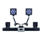
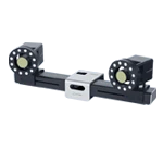
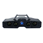
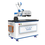
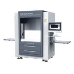
The XTOP3D XTOM stationary blue-light 3D scanner enables full-dimensional 3D inspection of mold bases directly at the machining station. By eliminating the need to transport the workpiece, it allows for the precise quantification of machining errors, providing reliable metrological data to guide mold adjustments and assembly.
I. Analysis of Blue-Light 3D Scanning Technology Selection
For the inspection of small-to-medium-sized precision injection mold bases, both traditional coordinate measuring machines (CMMs) and handheld laser scanners exhibit significant limitations. CMMs rely on discrete sampling, making it difficult to fully evaluate continuous surface features such as mold cavities or rounded corners. Furthermore, when dealing with hundreds of arrayed counterbored holes, the extensive programming and inspection workload cannot meet the requirements for rapid on-site verification in a workshop environment.
While handheld laser scanners offer high mobility—making them better suited for large components with less stringent accuracy requirements—they suffer from poor metrological reproducibility due to their dependence on manual operation and data stitching (alignment). When measuring precision guide-pin holes or reference surfaces on a mold base, the stitching process can easily introduce errors, and fine features such as small holes or slots are prone to data loss.
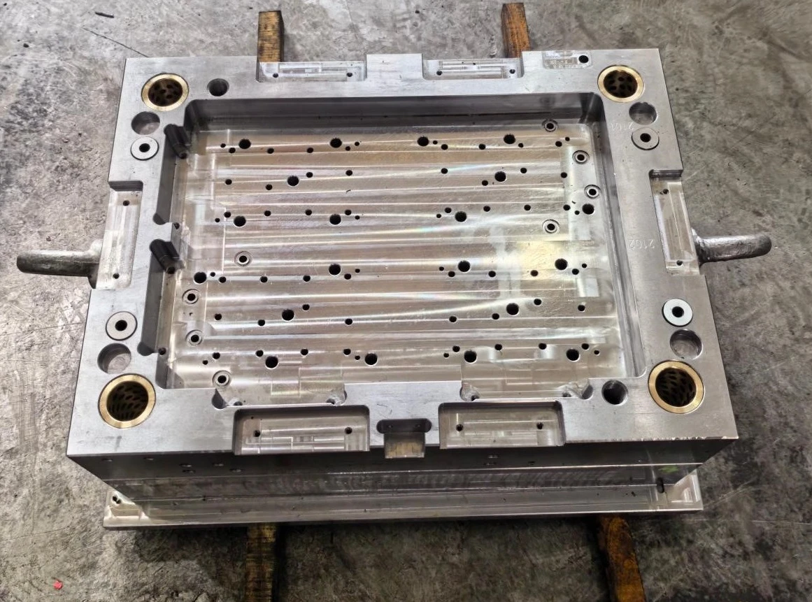
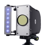
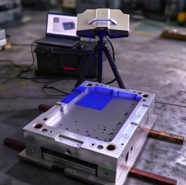
The XTOM scanner measures the mold base at the machining station.
The XTOM stationary blue-light 3D scanner is mounted on a tripod, eliminating the cumulative stitching errors often associated with handheld scanning. It delivers metrology-grade, reproducible measurement results, ensuring reliable inspection of critical features such as datums and guide-pin holes.
The blue-light fringe projection system effectively suppresses ambient light interference in workshop environments. With minimal preparation—applying a light dusting of powder and positioning reference markers—data can be captured directly at the workstation.
The system captures all details—including cavity surfaces, sharp edges, counterbored holes, and steps—in a single pass. It simultaneously handles both surface profile inspection and the measurement of multiple holes and slots, significantly boosting inspection efficiency for complex mold bases.
II. Blue-Light 3D Scanning Inspection Workflow
Apply a light dusting of powder to the workpiece surface and attach reference markers.
Mount the scanner on a tripod and perform a comprehensive 3D scan of the mold base from multiple perspectives.
Import the captured point cloud data into inspection software; align it with the CAD model based on the specified A, B, and C datums; perform a surface-to-CAD comparison; and generate a full-field color-coded deviation report.
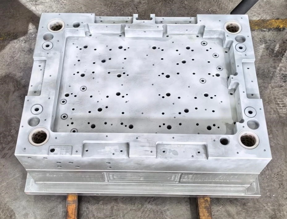
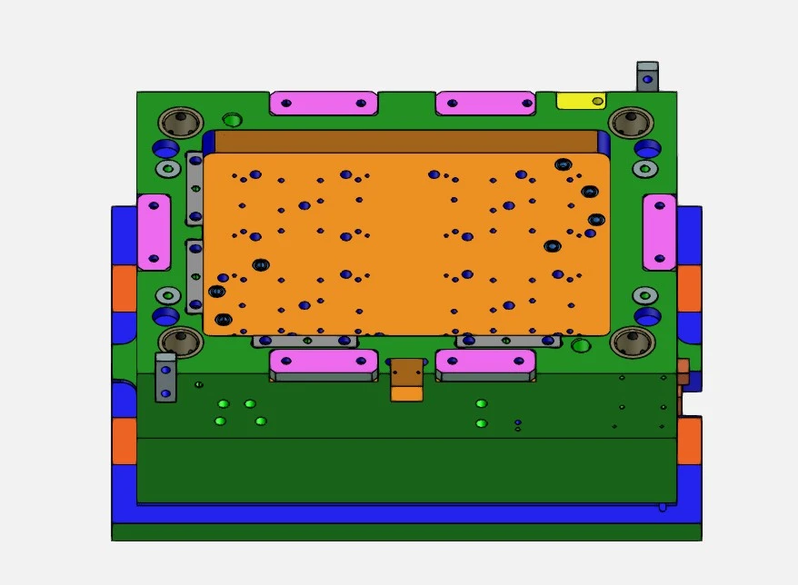
Original CAD model of the mold base
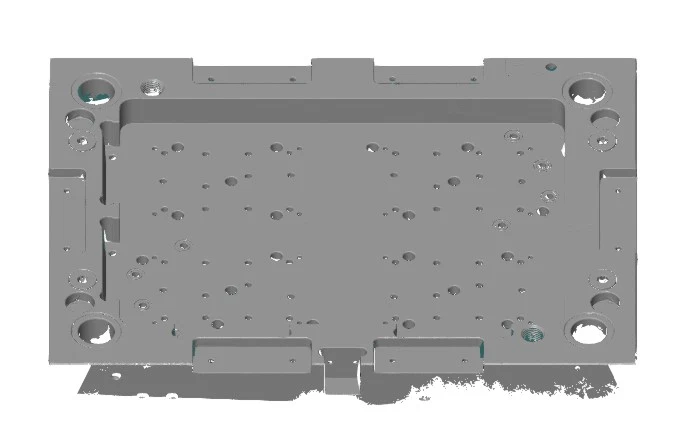
The nominal CAD model used for comparison.
III. 3D Full-Dimensional Inspection Results
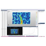
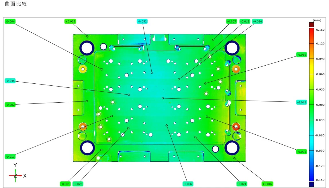
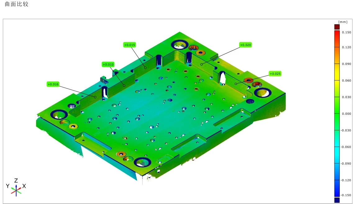
The 3D inspection output includes an ABC datum alignment report and a 2D/3D surface deviation color map, with the latter displaying the actual measured deviation values at specific inspection points.
ABC Datum Alignment Verification (Basis for Metrological Traceability)
The measured point cloud is aligned with the theoretical CAD model strictly according to the ABC datums specified in the engineering drawings. The deviations of the measured datum features relative to their theoretical coordinates are as follows: X = -0.000 mm, Y = +0.004 mm, and Z = +0.018 mm. By keeping these datum deviations within a minimal range, we ensure that the alignment coordinate system is perfectly synchronized with the manufacturing datums. This guarantees the accuracy and validity of the comparison data for cavities, steps, and hole patterns, serving as a prerequisite for the reliability of the inspection report.
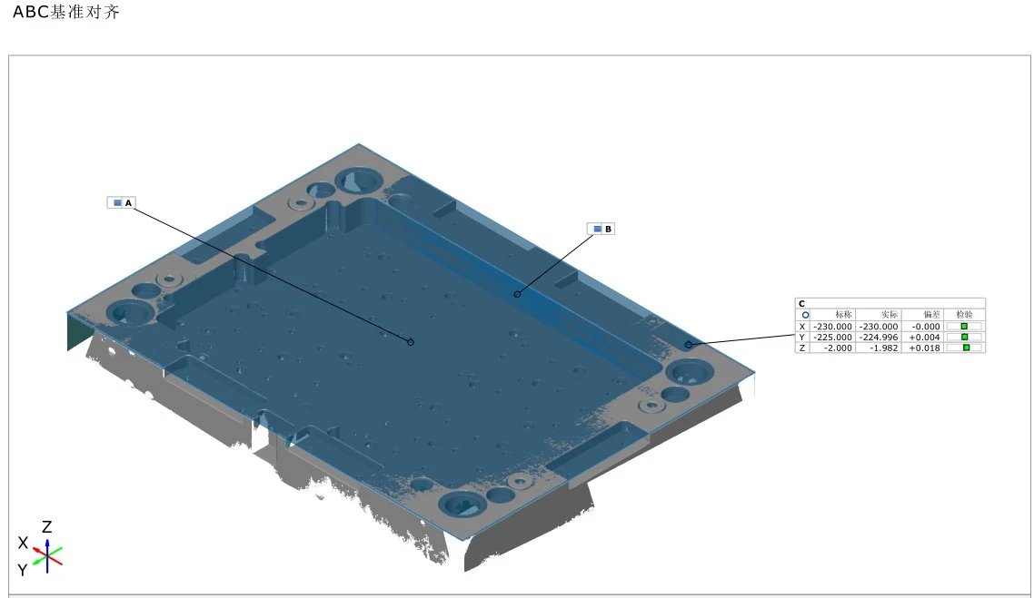
The measured surface model reconstructed from the XTOM scan.
Interpretation of Cavity and Surface Deviations
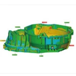
The color-coded deviation map shows that, for the main cavity and the locating step surfaces of the mold base, deviations across large areas are contained within a tolerance band of ±0.03 mm. This confirms that the CNC machining of the mold base generally conforms to the design specifications.
1) Negative deviation areas (-0.021 to -0.052 mm) are concentrated at the corners of the cavity and the edges of the steps, indicating minor localized over-cutting. The map allows for the precise identification of the location, extent, and magnitude of these over-cuts, distinguishing between localized over-cutting at rounded corners and general over-cutting along a side wall.
2) Positive deviation areas (+0.015 to +0.038 mm) appear primarily around the edges of holes and the corners of steps, representing localized residual material. Since this excess material is confined to specific edges, the map provides a clear visualization of its distribution, offering the bench technician precise guidance on where to perform grinding and the approximate amount of material to be removed.
3) Isolated out-of-tolerance points—concentrated around the guide pin holes and at the locating corners—are the result of localized machining fluctuations. As there is no large-scale surface deformation, these issues can be addressed through targeted, localized adjustments rather than requiring extensive rework of the entire mold base.
The Data Value of Hole Feature Analysis
Scanned point clouds provide a complete reconstruction of all arrayed counterbored holes, screw holes, guide slots, and locating steps. Based on the 3D scan data model—beyond simple surface-to-surface comparison—it is possible to batch-extract geometric dimensioning and tolerancing (GD&T) parameters, including hole diameters, positional accuracy, flatness, and parallelism.
Data-Driven Guidance for On-Site Production
Inspection reports serve as more than just archival records; they provide direct support for benchwork operations on the shop floor:
-
Positive deviation zones: Clearly identify areas requiring grinding and the specific material allowance to be removed, helping to prevent over-grinding.
-
Negative deviation (over-cut) zones: Use quantified deviation data to assess whether the discrepancy falls within acceptable assembly tolerances, determine where weld repairs are needed, and define the precise scope for such repairs.
-
This shifts the workflow away from relying on subjective, experience-based error estimation, ensuring that all rework is based on concrete, measured data.
IV. Application Value of 3D Inspection
1. Comprehensive Surface Quality Evaluation. By capturing a complete, continuous point cloud of the surface—including traditionally hard-to-inspect areas such as cavity corners, hole edges, and stepped features—the quality assessment evolves from checking isolated points to a full-surface digital evaluation of the workpiece.
2. Optimized Production Cycle. Small to medium-sized precision mold bases can be measured directly at the workstation, eliminating the time required for transport, clamping, and setup. Quantitative deviation data is generated immediately upon completion of machining, aligning with the rapid verification requirements of a mold-making workshop.
3. Reduced Trial-and-Error Costs. Deviation heat maps and precise measurement data pinpoint exactly where rework is needed and quantify the magnitude of the deviations. This minimizes repetitive trial-and-error, reduces material waste and time spent on corrective welding or secondary machining, and shortens the mold-fitting cycle.
4. Full Data Traceability. Point cloud files and deviation reports are archived in their entirety. By aggregating inspection data across multiple batches of similar mold bases, users can identify recurring deviation patterns—such as systematic offsets stemming from CNC programming or machine tool characteristics—to optimize machining parameters and improve consistency across production batches.
5. Quality Control Throughout the Entire Mold Lifecycle. Beyond the acceptance inspection of newly machined mold bases, this solution can also be used to monitor wear and deformation in molds already in service. By comparing current scans against historical data, users can quantify warping or wear, thereby shortening the time required for mold repair and refurbishment.