Aero-engine blisks, impellers, and blades are core components of propulsion systems. Their polished surfaces are highly reflective, and the blades themselves are thin-walled structures with complex, curved geometries—featuring leading and trailing edges less than 1mm thick. These components require micron-level precision for their aerodynamic profiles; any dimensional deviation can lead to a degradation in the overall aerodynamic performance of the engine.
Traditional coordinate measuring machines (CMMs) can only capture discrete points, failing to acquire complete surface data. Furthermore, physical contact by a probe can cause deformation in thin-walled components. Line-laser scanning, meanwhile, is susceptible to interference from highly reflective surfaces, resulting in significant noise and data gaps, as well as low overall inspection efficiency—making it inadequate for the comprehensive, full-dimensional quality inspection required for aerospace components.
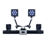
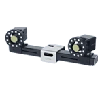
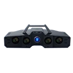
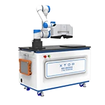
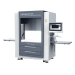
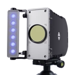
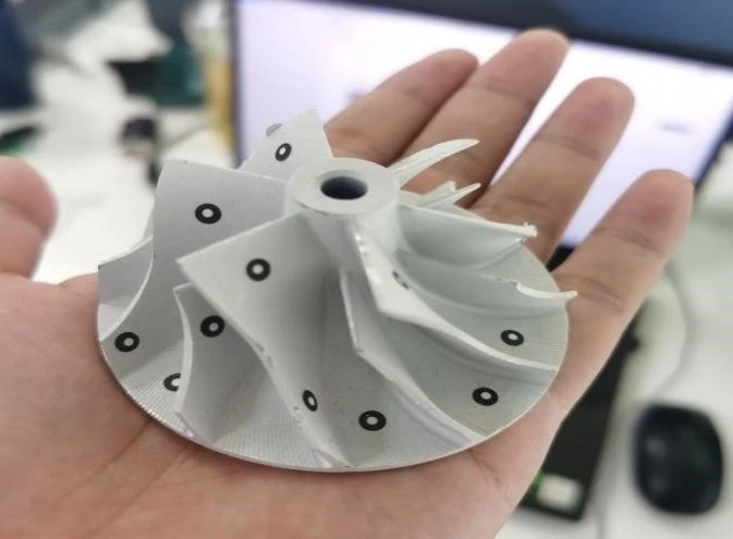
By utilizing the XTOP3D XTOM metrology-grade blue-light 3D scanner—which employs non-contact blue-light fringe projection technology—it is possible to capture complete 3D data of blisks, impellers, and blades. This enables CAD-to-part comparison, airfoil cross-section analysis, and edge curvature inspection, facilitating the digital quality verification of complex aerospace impeller-type components.
Challenges in Inspection
Interference from Highly Reflective Surfaces: Polished surfaces of titanium alloy or superalloy components reflect ambient light, often leading to data gaps and excessive noise when using conventional optical measurement methods.
Difficulty in Capturing Complex, Thin-Walled, and Fine Features: Components such as turbine blades feature extremely thin leading and trailing edges, as well as intricate details like root radii and damping platforms. Furthermore, aerodynamic profiles demand high precision regarding contour, twist angle, and chord width.
Risk of Deformation via Contact Measurement: The pressure applied by a contact probe can cause slight deformation in thin-walled blades, resulting in measurement errors.
Complexity in Multi-Surface Occlusion and Registration: Within the flow channels of an impeller, various curved surfaces obstruct one another, making it difficult to register scans taken from different sides. Achieving high overall accuracy requires the use of global reference points to align data from multiple perspectives.
Blue-Light 3D Scanning Inspection Solution
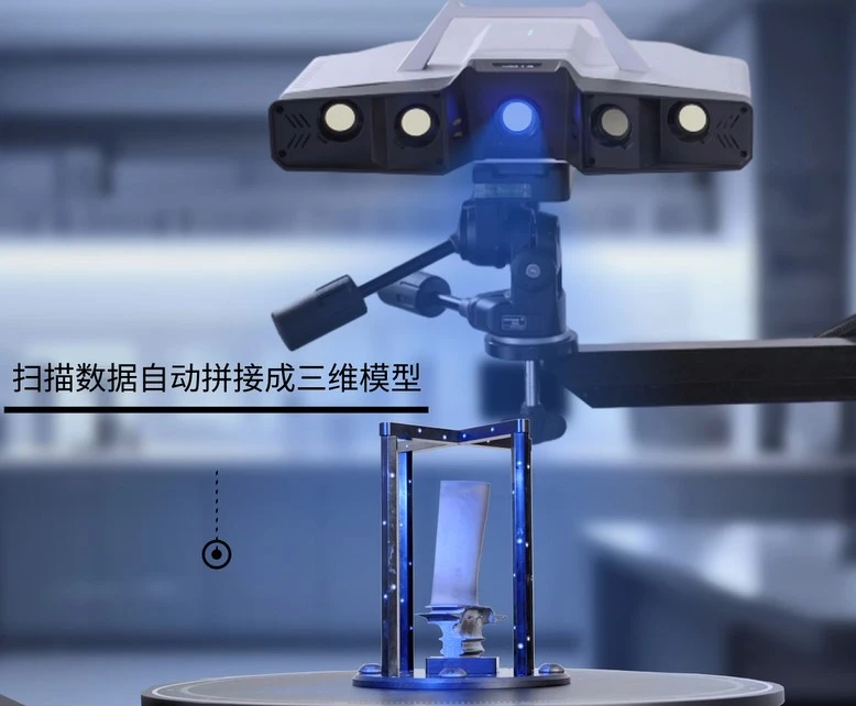
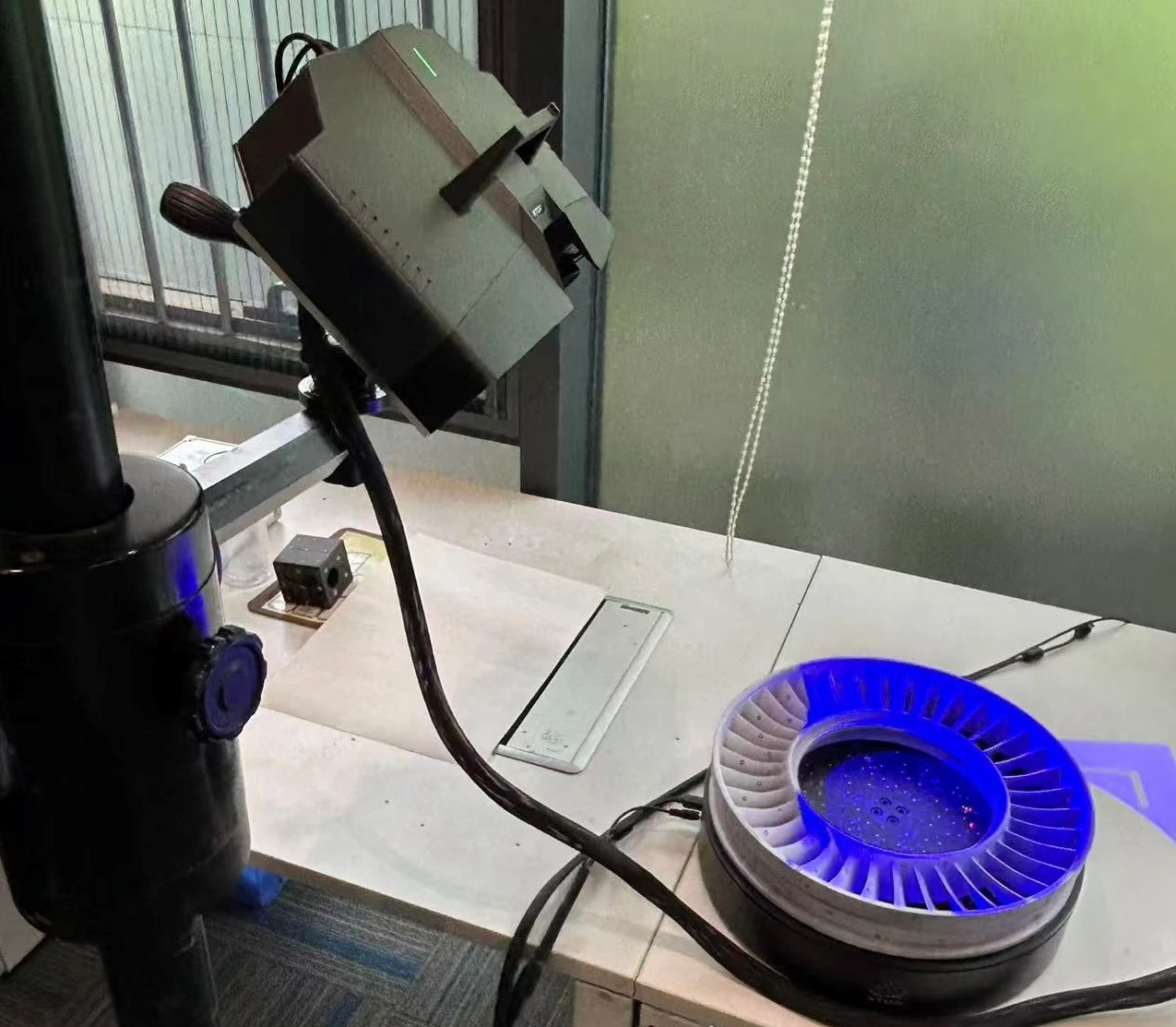
This solution utilizes an XTOM metrology-grade blue-light 3D scanner, featuring narrow-band blue-light projection technology. By employing a rotary table for multi-angle data acquisition and using global reference markers for precise alignment, the system captures the deformation of encoded fringe patterns via dual cameras. It then calculates the 3D coordinates of the component to generate a comprehensive, high-density point cloud.
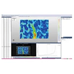
The scanned 3D model is imported into 3D inspection software, where it is automatically aligned with the theoretical CAD model to perform a full-surface color-coded deviation analysis. Cross-sectional profiles are extracted at various blade heights to analyze parameters such as chord width and twist angle. Additionally, the system identifies the leading and trailing edges of the blades, calculates the radius of curvature (R-value), and generates detailed 3D inspection data and reports.
3D Scanning and Inspection of Blisks (Bladed Disks)
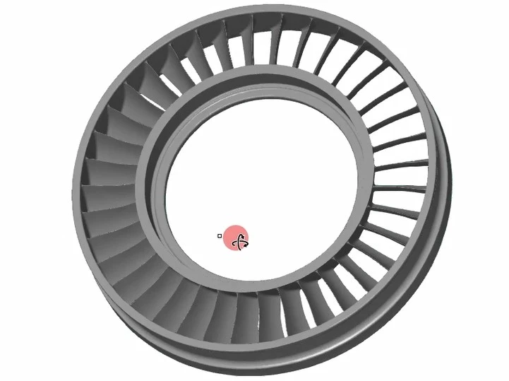
The aerospace blisk component is placed on a rotary table, where the blue-light scanner captures data from multiple angles. Global reference markers are used to stitch the data together, resulting in a complete point cloud that forms a 3D model of the blisk. This process accurately reproduces intricate details, such as the flow paths between blades and the fillets at the blade roots. The system ensures high data completeness—even for reflective surfaces—effectively preventing data loss typically caused by light reflection.
Once the 3D scan data is imported into the inspection software, it is automatically aligned with the CAD model. This enables the analysis of various parameters, including profile shape and position, twist angle, maximum profile thickness, chord length and angle, and the thickness of the blades at specific distances from the leading and trailing edges.
Propeller Blade Profile & Cross-Section Inspection
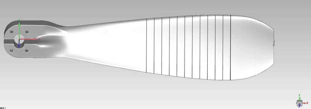
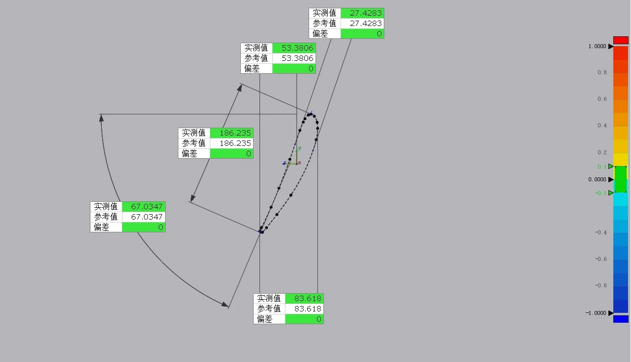
By performing multi-angle 3D scanning of a propeller blade, a complete 3D model is generated. Cross-sectional profiles are extracted at various heights along the blade span and compared against the theoretical CAD design. The system outputs measured values, reference values, and deviations for each control point, enabling a rapid assessment of whether the airfoil profile meets design tolerances. It also identifies defects—such as distortion on the suction side (back of the blade)—that could compromise aerodynamic efficiency.
This full-scale 3D inspection allows for the analysis of overall surface deviation, critical cross-sectional profiles, thickness distribution, leading/trailing edge radii, pitch and twist angles, chord length, width, and blade tip positioning.
3D Inspection and CAD Trend Analysis for Impellers
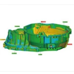
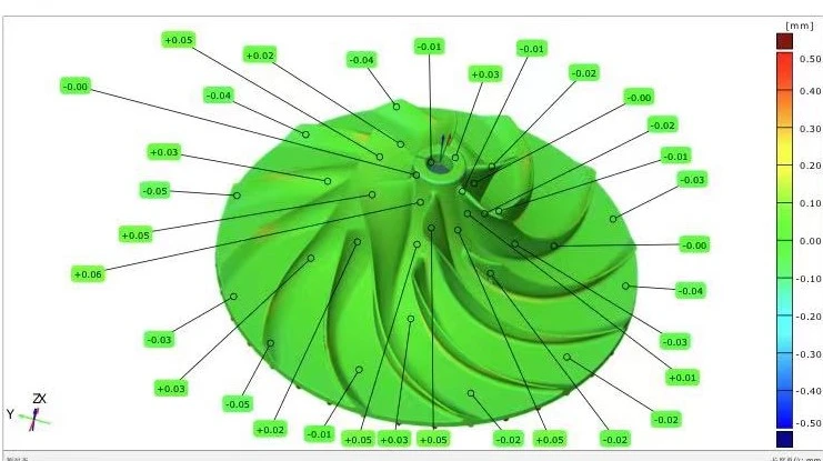
For impeller workpieces, a global point-cloud registration approach is employed. By comparing the 3D scanned model against the original CAD design, a color-coded deviation map is generated, providing a clear visualization of positive and negative deviations across the impeller blades and hub.
Through multi-dimensional deviation analysis using 3D inspection software, the color-coded map offers an intuitive overview of deviation distribution across the entire surface, while 2D cross-sectional curves allow for precise comparison of localized dimensional differences. This enables technical personnel to quickly grasp the nature of any errors and accurately pinpoint their root causes—such as issues with CNC machining parameters or tool wear.
Turbine Blade Airfoil Profile Inspection
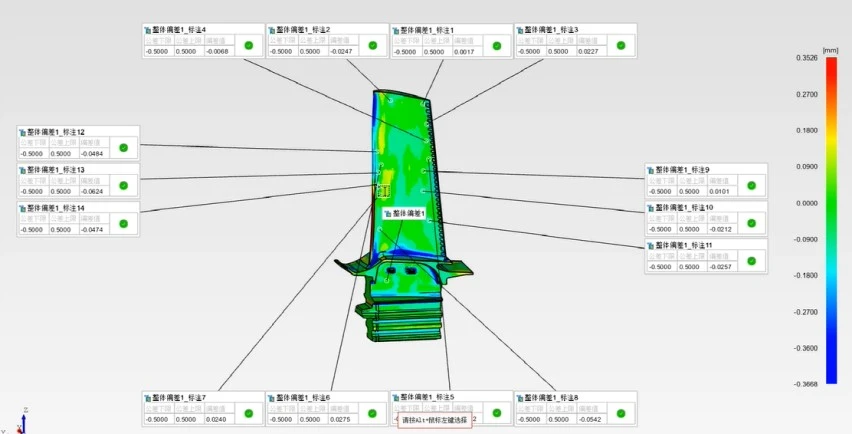
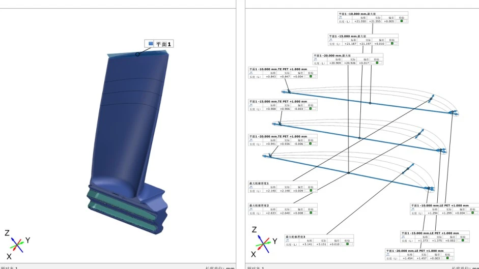
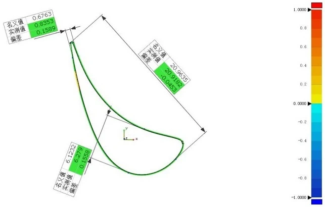
For turbine blades, multiple key cross-sections are selected along the blade span. 3D inspection software automatically aligns the blade with its CAD model to calculate the normal deviations between the actual surface and the theoretical model, while also measuring parameters such as chord width, twist angle, and root dimensions.
For the thin-walled, sharp-edged leading and trailing edges, a sub-pixel edge extraction algorithm is employed to precisely identify the edge profiles. The radii (R-values) of the leading and trailing edges are then determined through curve fitting, with the system outputting nominal values, measured values, and the corresponding deviations.
Inspection Results and Project Value
1. Full-Surface Data Acquisition: Unlike discrete-point measurements taken by CMMs (Coordinate Measuring Machines), blue-light scanning captures 3D data for the entire surface of a component. A color-coded deviation map provides an intuitive visualization of overall variance, enabling the detection of localized, minute distortions or profile deviations that might otherwise be missed.
2. Solutions for Thin-Walled Components: As a non-contact measurement method, it eliminates the risk of deformation caused by mechanical pressure on thin-walled blades. Furthermore, the blue-light system is resistant to ambient light interference; even for polished, reflective surfaces, a simple application of a developer spray is sufficient to obtain high-quality point cloud data.
3. Analysis of Critical Aerodynamic Parameters: The system automatically generates key aerospace-specific metrics—such as blade twist angle, chord width, trailing-edge radius, and cross-sectional profiles—facilitating rapid assessment of a component’s aerodynamic performance.
4. Significantly Enhanced Inspection Efficiency: Compared to traditional CMM methods, this approach drastically reduces inspection time, providing a digital foundation for the iterative refinement of five-axis machining processes and the quality acceptance of components.
In the micron-level quality control of aerospace impellers and blisks, metrology-grade blue-light 3D scanning overcomes the limitations of traditional measurement techniques. By balancing high precision, efficiency, and data completeness, it enables reliable metrological inspection of complex, thin-walled, curved components—ultimately contributing to the quality enhancement of aerospace propulsion parts.