Automotive lighting injection-molded parts feature complex geometries, including numerous free-form surfaces, thin-walled structures, internal ribs, snap-fits, mounting holes, and irregularly shaped cavities. Traditional inspection methods are limited to capturing discrete points, making it difficult to perform a full-surface analysis. Furthermore, thin-walled parts are prone to deformation under contact-based measurement, which prevents an accurate assessment of overall warpage or distortion—hinderances to effective mold iteration and process optimization.
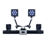
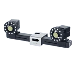
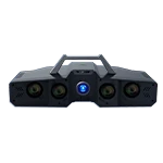
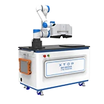
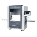
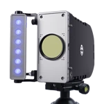
The XTOP3D XTOM blue-light 3D scanner utilizes non-contact blue-light fringe projection to capture a comprehensive 3D point cloud of the entire workpiece. By comparing the scanned data against the theoretical CAD model, the system provides an intuitive visualization of both global and local dimensional deviations. This enables high-precision, full-dimensional, digital inspection, delivering robust data support for trial-mold verification, quality control, mold modification, and process optimization.
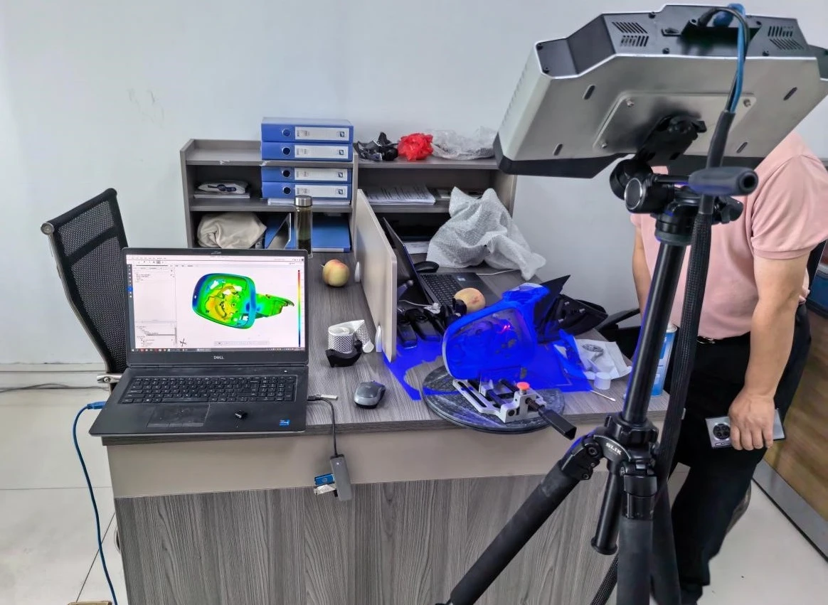
Automotive lighting injection-molded parts and housings feature complex geometries and require extremely high dimensional precision. Subsequent processes, such as assembly and overmolding, are highly dependent on consistent dimensions. Blue-light 3D scanning technology offers the following advantages:
Suitable for thin-walled injection-molded parts: Non-contact data acquisition ensures no deformation caused by mechanical pressure, guaranteeing the accuracy of the measurements.
Comprehensive coverage of complex structures: It captures data from areas often inaccessible to traditional inspection methods—such as curved surfaces, ribbed mesh structures, deep cavities, snap-fits, and small holes—enabling true full-dimensional inspection.
Visualization of deviations for efficient troubleshooting: It provides a clear view of global warpage and deformation, allowing for the rapid identification of areas that fall outside of tolerance specifications.
Analysis of overall form and GD&T: Beyond analyzing general deformation trends, the technology can extract specific Geometric Dimensioning and Tolerancing (GD&T) parameters—including distances, angles, and positional tolerances for holes, snap-fits, and mounting surfaces.
Digital traceability: 3D scan data and inspection reports are fully archived, supporting mold trial verification, mold adjustments, and quality sampling during mass production. This helps shorten the mold-trial iteration cycle and improves the yield rate of components.
Case 1: 3D Inspection of an Injection-Molded Rearview Mirror Housing
Inspection Requirements
The exterior of the housing features a complex, free-form surface with high curvature, while the interior contains a dense arrangement of locating holes, snap-fits, reinforcing ribs, and mounting bases, characterized by numerous internal cavities and channels. During production, it is necessary to verify the overall contour deformation, the positional accuracy of holes, and deviations in assembly mating surfaces to ensure precise fit and proper assembly gaps for the rearview mirror housing.
Inspection Process
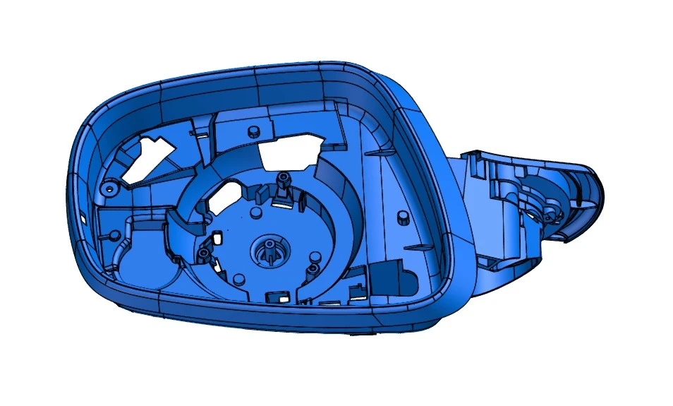
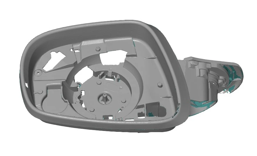
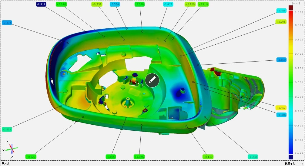
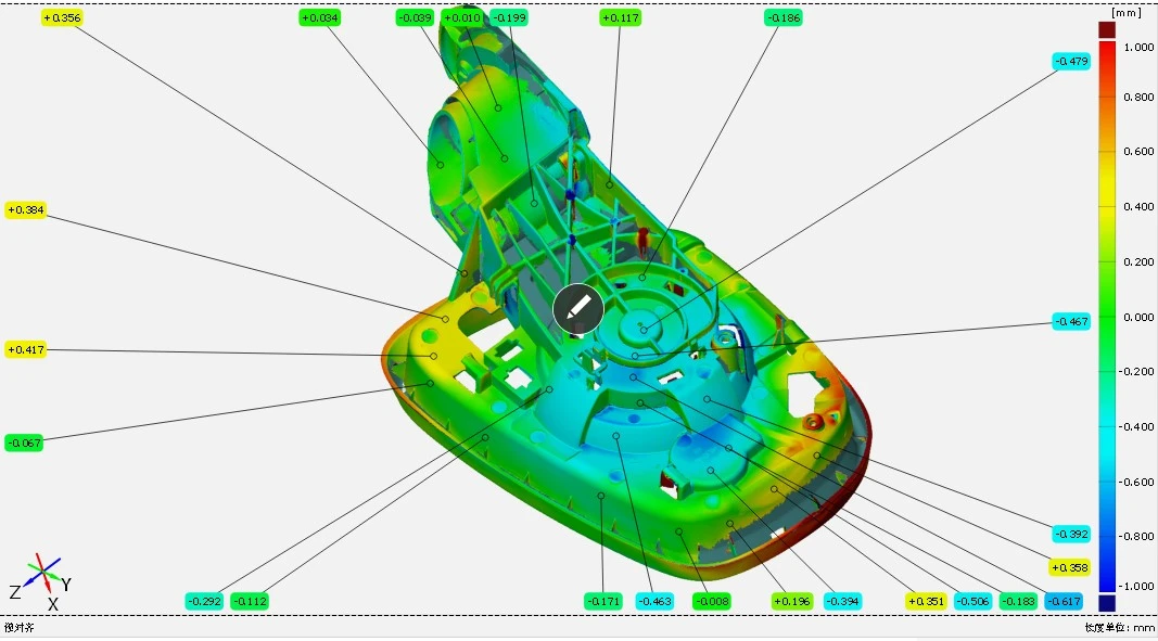
The rearview mirror housing is placed on a rotary fixture platform. An XTOM blue-light 3D scanner is used to capture 3D point cloud data of both the internal and external structures, generating a high-precision scan model. This model is then imported into 3D inspection software, where it is aligned with the original CAD design model. A comprehensive surface-to-surface comparison analysis is performed, and theoretical values, measured values, and deviations for critical features are extracted.
Inspection Results and Application Value
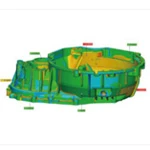
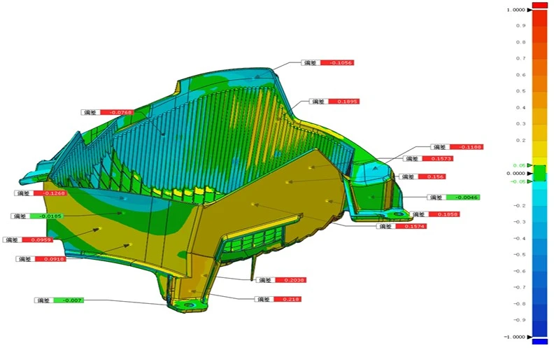
This method enables intuitive analysis of deformation distribution across the outer contour of the housing, the internal cavity base, and the areas surrounding various mounting holes. Each measurement point provides a direct output of deviation values in millimeters, offering a comprehensive representation of the workpiece’s overall warping trend—far surpassing the limitations of data from a few discrete points.
Application Value:
1. Enables comprehensive, full-dimensional inspection of complex internal and external surfaces, snap-fits, and hole positions on a housing in a single operation.
2. Rapidly identifies areas that fall outside of tolerance specifications, providing guidance for adjusting injection molding processes and performing mold modifications.
3. Captures actual deviations on assembly mating surfaces, allowing for the prediction of assembly gaps and potential interference risks, thereby reducing the need for physical trial assemblies.
Case 2: 3D Inspection of Complex Grid-Rib Structures in Injection-Molded Automotive Lighting Components
Inspection Requirements
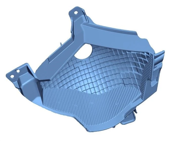
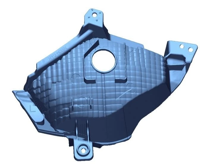
The automotive lighting component features a surface covered with a dense, intricate grid of ribs, complex curved surfaces, mounting bosses, and positioning through-holes. The grid ribs are fine and closely spaced, with varying thicknesses. The inspection requires evaluating the overall deformation, the profile accuracy of the grid-rib surfaces, and the positional accuracy of the mounting bosses, specifically to assess deformations caused by injection-molding shrinkage.
Inspection Process
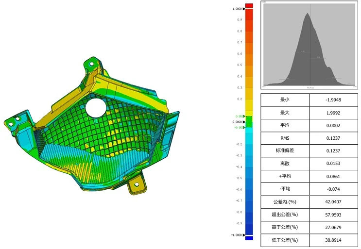
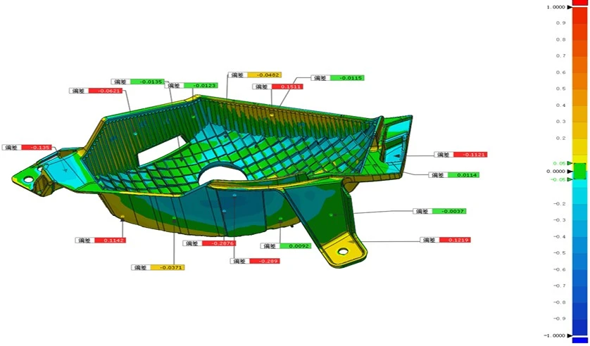
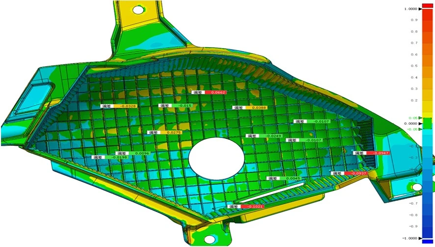
An XTOM blue-light 3D scanner is used to perform a comprehensive scan of the component, capturing even the fine grid structures and complex, multi-depth curved surfaces with high precision. The scanned model is then aligned with the CAD design model. The software calculates the overall deviation distribution, allowing for the selection of critical features—such as grid surfaces, mounting bosses, and holes—to output specific deviation data for each location.
Inspection Results and Application Value
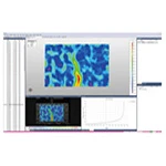
The inspection results reveal the proportion of areas on the workpiece that fall outside specified tolerances—categorized into regions exceeding the upper limit, falling below the lower limit, or remaining within tolerance. This provides an immediate, clear overview of any deformation in areas such as the grid-reinforced surfaces, corners, and mounting brackets.
Application Value:
1. Captures minute features of ribs and grids, enabling comprehensive inspection of complex, fine-scale structures.
2. Generates statistical reports that quantify overall deformation, facilitating the assessment of injection molding shrinkage and the adequacy of cooling processes.
3. Rapidly identifies out-of-tolerance locations for support legs and mounting bosses, providing guidance for mold compensation adjustments to enhance part consistency.
Case Study 3: 3D Inspection of Snap-fit Features on an Injection-Molded Headlight Base
Inspection Requirements
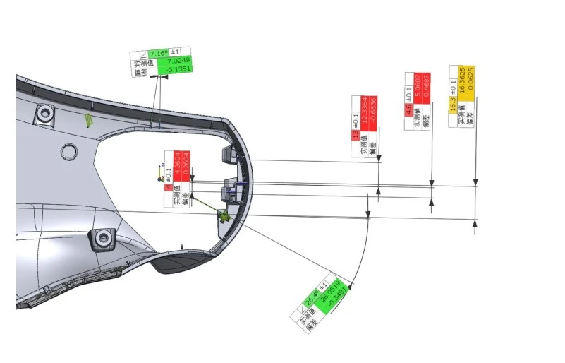
For the injection-molded headlight base, the primary focus is on the dimensions and geometric tolerances of the snap-fit structures. Any dimensional deviation in these snap-fits directly impacts the reliability of the assembly and securement of the headlight unit. A lens with a 200 × 150 mm scanning field of view was selected to ensure the entire component could be captured in a single scan.
Inspection Process
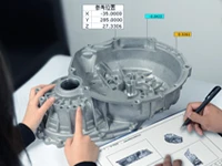
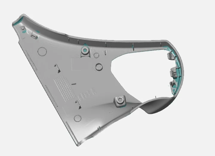
An XTOM blue-light 3D scanner was used to scan the base component, accurately reconstructing the geometry of the snap-fit features. The scan data was then imported into inspection software and aligned with the digital model (CAD). Key geometric tolerances—such as angles, distances, and positional accuracy—were extracted for the snap-fits and mounting posts. The final output consists of inspection screenshots annotated with measured values, theoretical (nominal) values, and the corresponding deviations.
Inspection Results and Application Value
Comprehensive 3D data of the clip locations is successfully acquired, providing inspection results for geometric tolerances—such as clip angle, distance, and positional accuracy—to precisely evaluate whether the clips meet assembly tolerance requirements.
Application Value:
1. High-detail scanning capability: Captures intricate features such as narrow snap-fits, overcoming the challenges associated with inspecting micro-assembly structures.
2. Targeted output of geometric dimensioning and tolerancing (GD&T) for critical assembly features, focusing on the aspects of greatest importance to the client.
3. Lenses designed for small-to-medium fields of view are perfectly suited for small and medium-sized automotive lighting injection-molded parts; the scanning range aligns with the dimensions of the workpieces, ensuring high inspection efficiency.
Leveraging the non-contact, high-density, and full-field data acquisition capabilities of blue-light 3D scanning technology, the quality control process for complex, injection-molded automotive lighting components—featuring intricate contours—is upgraded from "spot-check" sampling to comprehensive 3D surface quality control. This ensures that inspection results are visual, traceable, and quantifiable.
In terms of practical application, this solution accelerates the iterative trial-molding process for new automotive lighting products, reduces the costs associated with repeated mold modifications, helps preemptively avoid assembly-fit issues, stabilizes injection-molding yields, and meets the stringent high-precision inspection requirements set by automotive OEMs for optical surfaces and assembly profiles.