Materials and components in the aerospace and energy equipment sectors are frequently subjected to complex service environments characterized by coupled thermal-mechanical loading. Under high-temperature conditions, materials undergo plastic flow, strain localization, and necking, eventually leading to fracture; component failure often originates from these early-stage deformation-induced damages.
By integrating Digital Image Correlation (DIC) with thermal (infrared) imaging, it is possible to analyze the evolution of full-field deformation, strain, and temperature in a time-correlated manner. This approach captures the entire progression—from uniform plastic deformation and strain localization to necking, damage, and final fracture—across various temperatures. It provides quantitative experimental data essential for the development of new materials, the optimization of heat treatment processes, and the validation of coupled thermal-mechanical simulations.
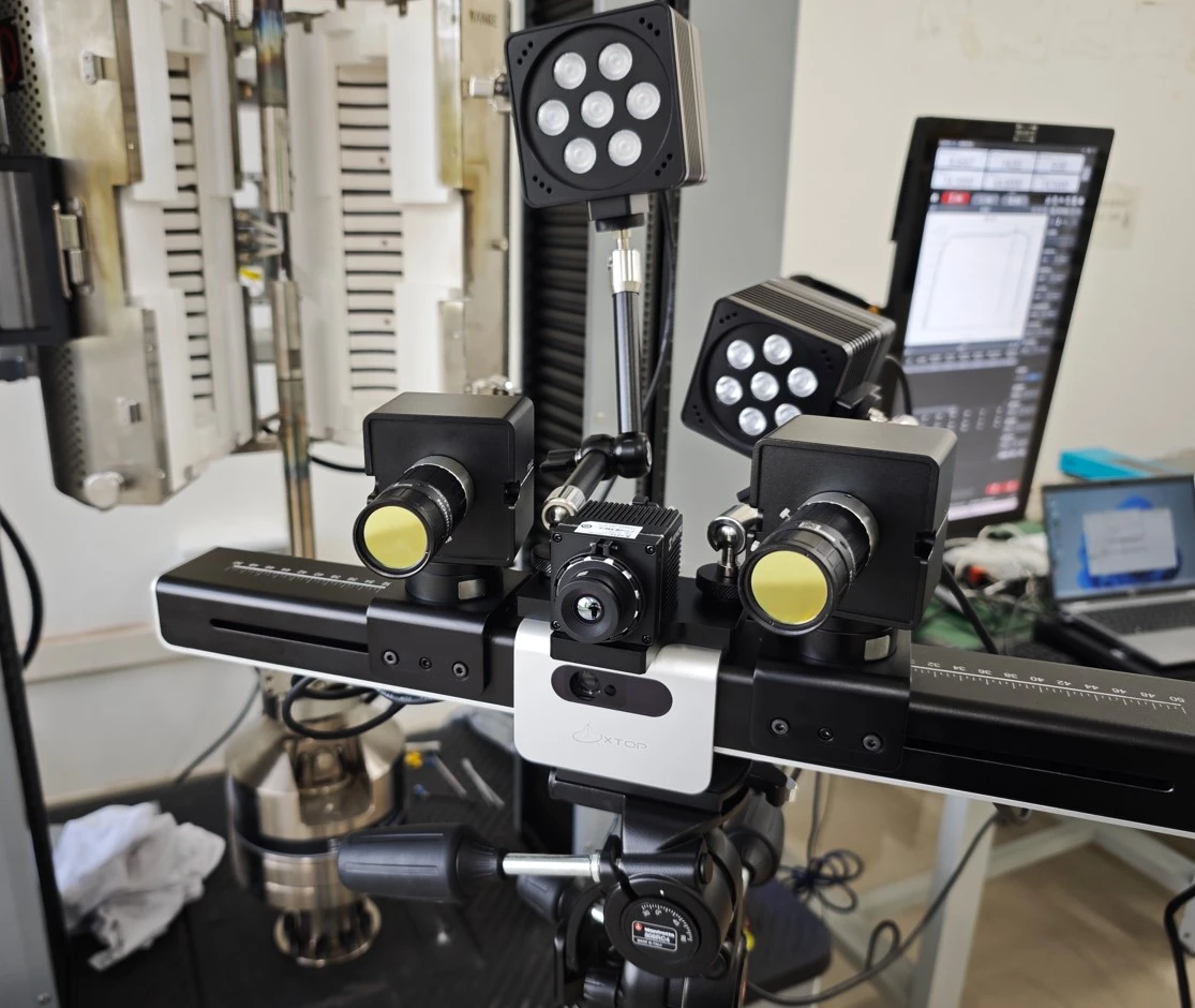
Integrated Testing Using DIC Technology and Thermal Imaging (Infrared) Cameras
I. Current Pain Points in High-Temperature Tensile Testing
Contact-based testing methods only provide average values for a small, localized area. Consequently, they struggle to capture non-uniform damage processes—such as early-stage localized plasticity, strain concentration, or the onset of necking—occurring on the specimen surface.
Furthermore, the presence of temperature gradients within high-temperature furnaces makes it difficult to determine the true surface temperature of the specimen, preventing the establishment of a direct correlation between deformation behavior and actual temperature.
Additionally, high-temperature testing is subject to various measurement interferences, including optical distortion caused by observation windows, disturbances from thermal air currents within the furnace, and grayscale drift in speckle patterns due to intense thermal radiation. Without targeted correction, these factors lead to distorted measurement data.
II. Integrated Testing Solution: DIC Technology Combined with Thermal Imaging
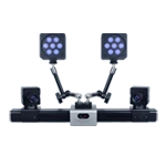
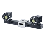
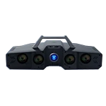
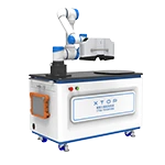
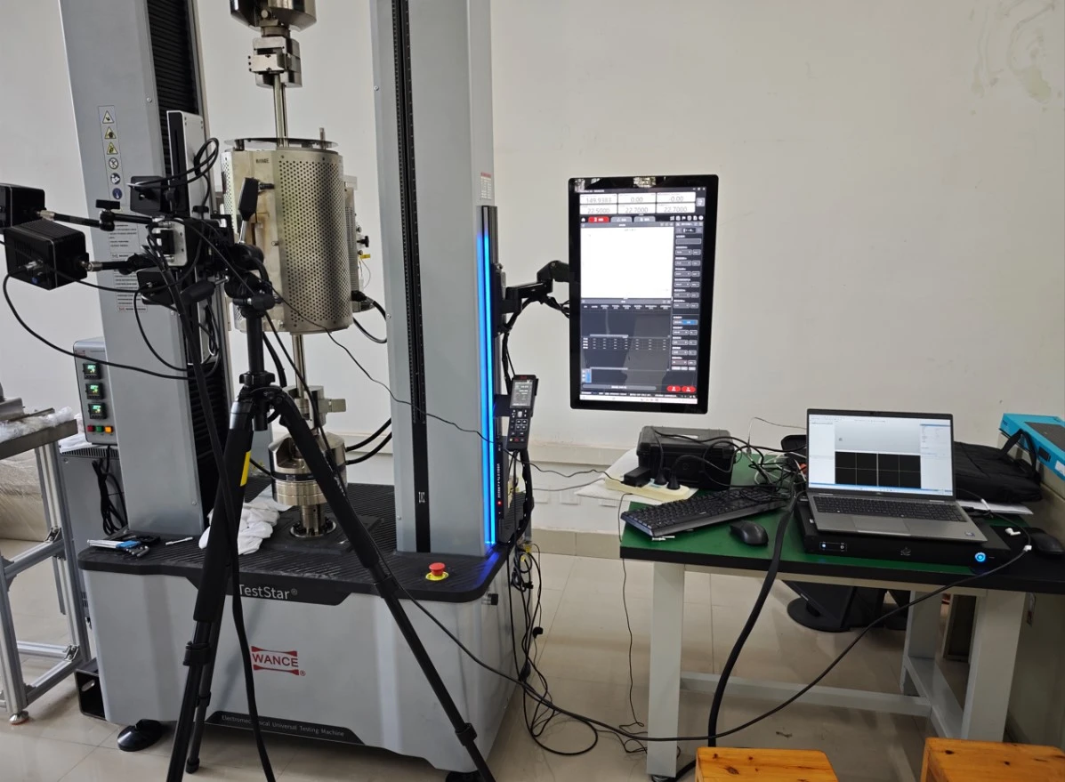
To address these limitations, an integrated testing solution has been developed, combining the XTOP3D XTDIC 3D strain measurement system with a thermal imaging camera.
Synchronization Mechanism: Hardware-level synchronization ensures that load data from the testing machine, visible-light DIC images, and infrared thermal images are aligned with millisecond-level precision. All data share a unified timestamp, enabling a chronological, side-by-side analysis of deformation/damage and temperature fluctuations.
By utilizing DIC and thermal imaging, this non-contact approach captures full-field displacement and strain evolution while simultaneously recording the specimen's true surface temperature over time—effectively filling the gaps in multi-dimensional data left by traditional testing methods.
III. Precision DIC Measurement Under High-Temperature Conditions
In high-temperature tensile DIC testing, key requirements for obtaining reliable data on deformation, damage, and temperature include compensating for viewing-window distortion, ensuring stable tracking of high-temperature speckle patterns, and achieving precise temporal synchronization across multiple devices.
1. VRO (Viewing-Window Refraction Optimization) Calibration: Eliminates systematic errors caused by light refraction through the glass observation windows of high-temperature furnaces, ensuring measurement accuracy for displacement and strain across multi-stage temperature tests.
2. Robust Sub-pixel Speckle Tracking for High Temperatures: Effectively mitigates grayscale fluctuations induced by thermal radiation and convective heat currents, enabling stable capture of high-gradient strain and damage zones—even during the necking phase.
3. Hardware-Based Temporal Synchronization: Ensures strict alignment of the timelines for mechanical loading, DIC imaging, and thermographic data, facilitating the analysis of the temporal correlation between deformation and temperature.
4. Full-Field Post-Processing and Analysis: Generates displacement and strain contour maps and extracts various temporal evolution curves, which can be directly utilized for benchmarking and validation against finite element (FE) simulations.
IV. Multi-Stage Temperature (200°C–1000°C) Testing Case Study for Metallic Materials
Test Objectives
1. Conduct high-temperature tensile testing of metallic materials across multiple temperature stages (200°C–1000°C) to verify the measurement accuracy of Digital Image Correlation (DIC) technology when viewing through a high-temperature observation window.
2. Capture the entire deformation and failure process—from elastic deformation, uniform plastic deformation, and strain localization to necking, damage, and eventual fracture—at various temperature levels.
3. Utilize synchronized timestamps to correlate the specimen’s strain and damage state with its surface temperature over time, thereby revealing the influence of temperature on the material’s plasticity and damage evolution behavior.
Specimen Information
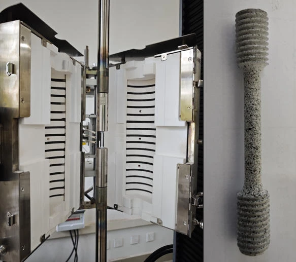
Specimen Type: Standard cylindrical tensile specimen for high-temperature metallic materials.
Pre-treatment: The gauge section of the specimen is coated with a high-temperature-resistant inorganic speckle pattern to ensure that the speckle features remain stable and trackable under high-temperature conditions.
Testing Equipment
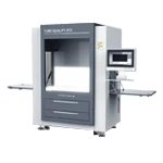
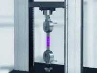
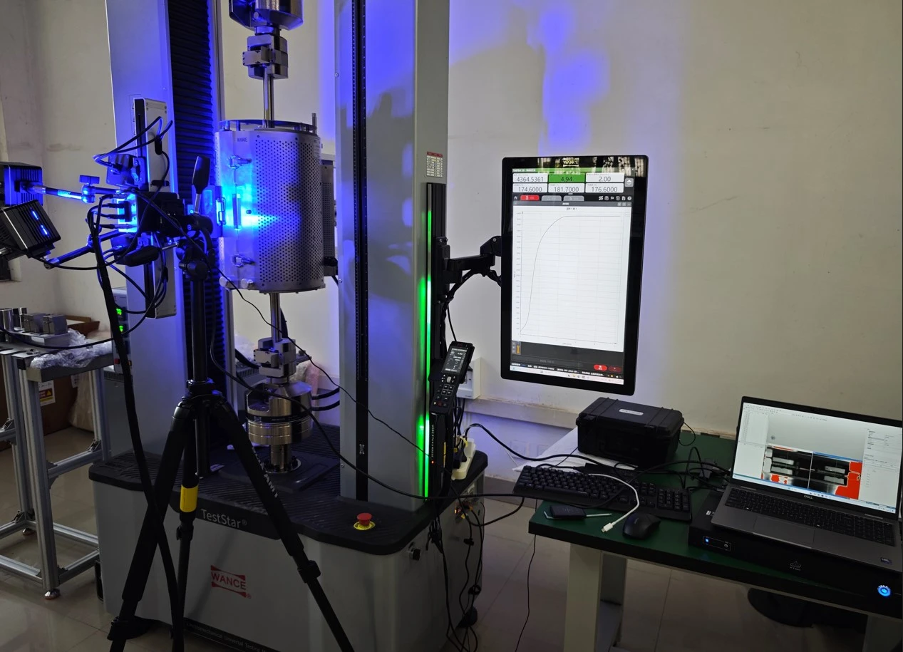
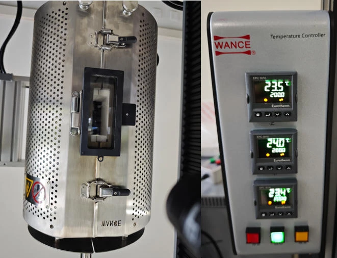
Mechanical testing equipment: Universal high-temperature tensile testing machine, equipped with a high-temperature resistance furnace.
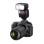
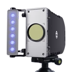
Optical equipment: XTDIC 3D strain measurement system (1200-megapixel resolution, 50 mm lens, 64 mm × 48 mm field of view); infrared thermal imaging camera.
Test Conditions
Temperature steps: 200°C, 400°C, 600°C, 800°C, 1000°C
Test Procedure: Heat to the target temperature → maintain the temperature until thermal equilibrium is reached within the furnace → initiate tensile loading; trigger data acquisition simultaneously across the DIC system, thermal imaging camera, and testing machine hardware; complete tensile tests sequentially for each temperature level.
Experimental Results and Damage Evolution Analysis
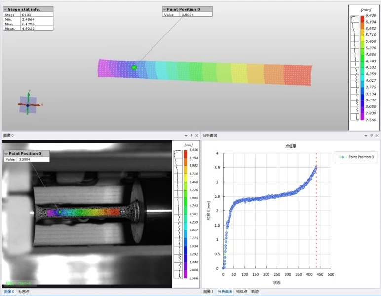
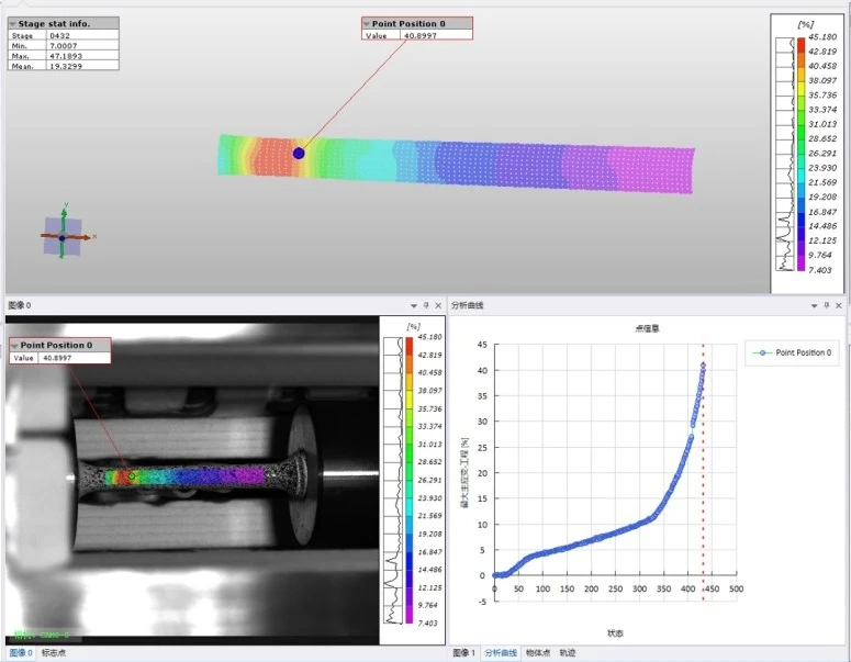
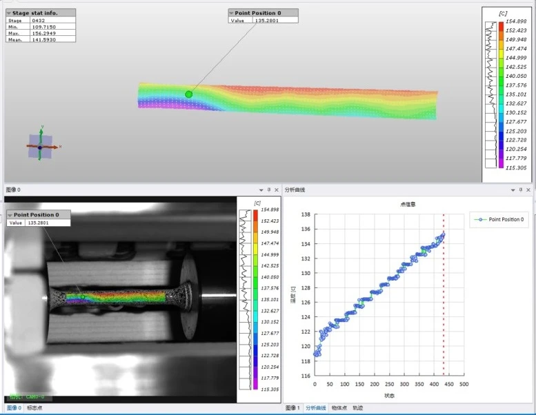
Even under the demanding conditions of a high-temperature furnace—viewed through a glass observation window—Digital Image Correlation (DIC) technology consistently provides full-field displacement and strain data. It clearly characterizes the evolution of plastic deformation, strain localization, and necking-related damage at various temperatures, with integrated analysis performed in conjunction with time-resolved thermal imaging.
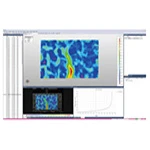
From top to bottom: DIC full-field displacement map, full-field principal strain map, and synchronized thermal imaging temperature field map.
1. Displacement Map
The axial displacement gradient is continuous and symmetric, and the deformation within the specimen’s gauge length is uniform, with no signs of unilateral eccentric loading. This confirms that the specimen is well-aligned within the grips and that the loading conditions are valid, providing a reliable foundation for the strain results.
2. Principal Strain Contour Plot
This tool enables the direct identification of strain concentration zones and strain gradients, allowing for the detection of the onset of strain localization—well before necking becomes visible to the naked eye. It also supports the extraction of local strain-versus-time data, which can be used for the validation and benchmarking of simulation models.
3. Thermal Imaging Temperature Field Map
This involves quantifying the axial and radial temperature gradients within the gauge section, verifying the actual temperature uniformity of the specimen, and distinguishing between the temperature control setpoint and the specimen's true temperature. These data are used to evaluate the uniformity of the thermal field and to correct deviations in constitutive testing caused by temperature-related coupling effects.
Load-Displacement Curves with Multi-Source Temporal Synchronization
By utilizing a unified timestamp, key events—such as the elastic region, strain hardening phase, peak load, necking instability, and fracture—can be precisely correlated with synchronized strain and temperature data. This enables the accurate identification of the onset and location of plastic instability, along with the corresponding actual temperature, resulting in a coupled load-deformation-temperature temporal dataset.
V. Case Summary
The integrated testing solution, combining Digital Image Correlation (DIC) with thermal imaging, employs VRO (Virtual Refraction Optics) calibration and robust high-temperature speckle tracking algorithms. These techniques effectively mitigate interference from glass refraction, thermal air currents within the furnace, and high-temperature grayscale drift, ensuring high-precision displacement and strain measurements in high-temperature environments.
Hardware-level temporal synchronization between the DIC and thermal imaging cameras—facilitated by a unified timestamp—enables the correlation of deformation/damage processes with temperature over time.
This DIC-based approach allows for the multi-dimensional acquisition of full-field displacement and strain data for metals under various temperature steps, capturing the entire evolution of damage, including strain localization and necking. By integrating thermal imaging data, researchers can perform thermo-mechanical temporal analysis—a capability well-suited for investigating the mechanisms of advanced high-temperature materials, optimizing heat treatment processes, and benchmarking thermo-mechanical coupled simulations—thereby providing a comprehensive, multi-dimensional, and quantitative experimental methodology.