Precision injection-molded parts are widely used in consumer electronics and smart devices. These components often feature intricate, small-scale structures such as recessed button housings, snap-fit ribs, cruciform positioning pins, screw bosses, and deep-cavity or bent geometries. Due to their compact size and non-uniform wall thickness, it is difficult to fully characterize the shrinkage and warpage that occur during the molding process. Furthermore, traditional measurement methods—such as using calipers or coordinate measuring machines (CMMs) for discrete point sampling—are often inadequate for inspecting internal cavities or fine rib features.
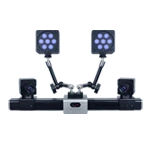
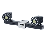
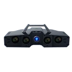
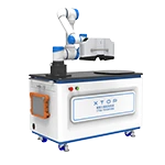
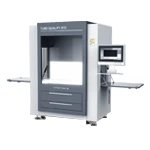
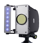
In this application, the XTOP3D XTOM-12M—a fixed, four-camera blue-light 3D scanner (configured with a 200×150 mm measurement field and an automated rotary table)—was used to scan two types of small, precision-molded plastic components: a snap-fit button assembly and a plastic housing. By capturing comprehensive surface data and performing a best-fit alignment against the original CAD models, the system generated full-surface color-coded deviation maps, along with specific deviation measurements at critical locations. These results were then used to evaluate molding quality and verify the system’s micron-level inspection accuracy.
I. 3D Inspection of Small-Sized Precision Injection-Molded Parts
1. Inspection Objective
A fixed-position, four-camera blue-light 3D scanner (XTOM-12M) is used to perform full-dimensional 3D inspection on two types of precision injection-molded components. By analyzing geometric and dimensional deviations, the process evaluates the molding quality of plastic housings and small snap-fit components.
2. Inspection Equipment
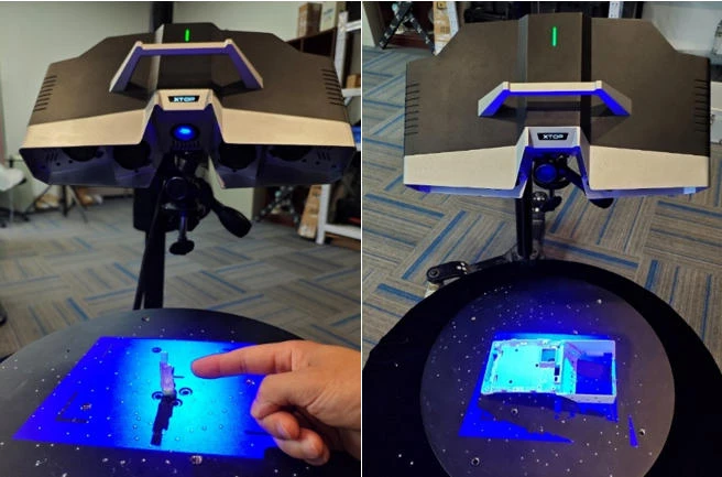
Scanning System: XTOM-12M (four-camera configuration; measurement field of view: 200 × 150 mm), equipped with a motorized rotary table.
3. Inspection Specimens
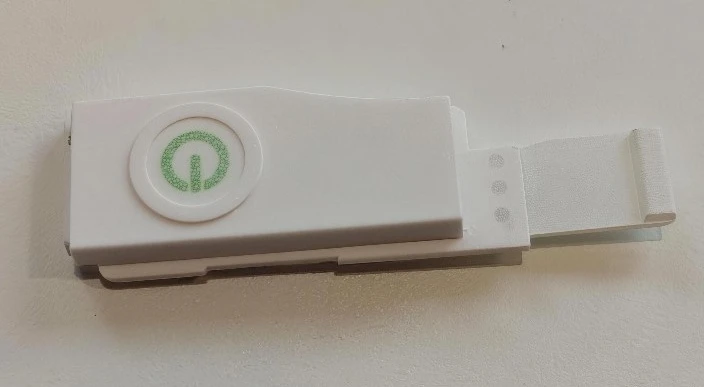
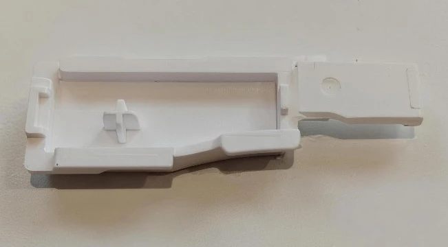
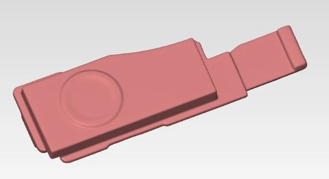
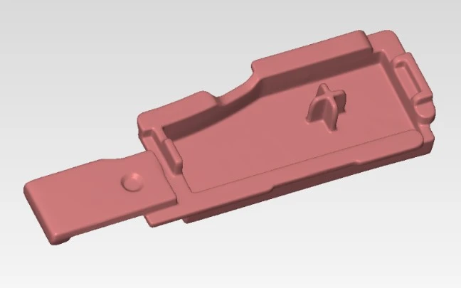
Specimen 1: A small plastic snap-fit button assembly—a white injection-molded part featuring button-labeling surfaces, internal snap-fit ribs, cross-shaped positioning posts, and recessed grooves. As a small, intricate component, it serves primarily to verify the system’s capability to capture fine, complex structural details.
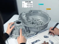
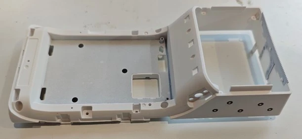
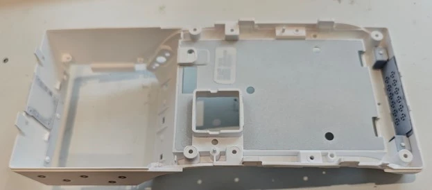
Workpiece 2: A plastic housing featuring multiple screw bosses, mounting holes, reinforcing ribs, and deep, recessed cavities. Due to its complex structure, it is primarily used to verify scanning and data acquisition capabilities for both the internal and external cavities of the housing.
4. 3D Scanning and Inspection Process
Place the workpiece on a motorized rotary table equipped with reference markers, ensuring the entire workpiece falls within the scanner's field of view. Data is captured using blue-light fringe projection; the rotary table allows for multi-angle acquisition, capturing all features of the workpiece, including its external surfaces, internal cavities, and structural ribs.
For Workpiece 1 (a small snap-fit component), multi-angle scanning is used to fully capture intricate features such as grooves, cross-shaped positioning posts, snap-fit tabs, and the recessed areas around circular buttons. For Workpiece 2 (a plastic housing), multi-view rotary scanning is employed to capture the outer surfaces, internal cavity walls, screw bosses, apertures, and curved corners.
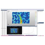
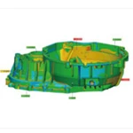
The resulting 3D mesh model is imported into 3D inspection software, where it is optimally aligned with the original CAD model. A 3D deviation analysis is then performed, generating a color-coded deviation map (heat map) along with specific numerical deviation values for measured points.
II. Interpretation of Inspection Results for Precision Injection-Molded Parts
Workpiece 1: Small Plastic Snap-Fit Button Assembly
Data Integrity
The reconstructed mesh shows that the circular recessed platform, outer contours, and edge snap-fits of the button are fully captured. Fine features—such as internal grooves, cruciform alignment posts, positioning holes, and snap-fit slots—are all present with no loss of detail. The mesh surface is smooth, free of large gaps or missing areas, and the outlines of the reinforcing ribs are clearly defined; the data quality meets the requirements for deviation analysis.
Deviation Analysis
The majority of the part’s surface appears green, indicating that the as-molded dimensions align well with the theoretical CAD model. Deviations are concentrated along the edges, the tips of the snap-fits, and the periphery of the recessed areas for buttons, manifesting as localized positive or negative deviations. Some localized deformation is observed in thin-walled sections, such as snap-fits and locating pins. Deviations at critical assembly interfaces remain generally within an acceptable range, with no instances of significant, widespread out-of-tolerance conditions.
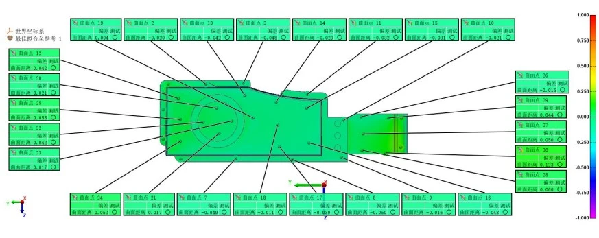
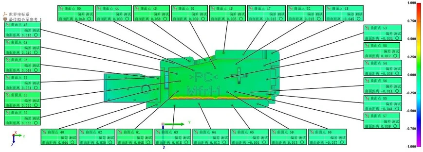
Root Causes and Process Implications: Deformation in thin-walled sections stems from differential shrinkage rates between these thin areas and the thicker main body during the cooling phase of the injection molding process. Features such as snap-fits and locating pins—critical for assembly—often exhibit localized deformation that goes undetected when sampling is limited to primary reference surfaces; this creates a risk where individual features may pass inspection, yet the part fails during assembly. The comprehensive surface deviation data obtained here can be used to directly refine packing and cooling parameters, thereby minimizing deformation in thin-walled regions.
Workpiece 2: Plastic Housing
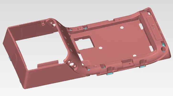
Data Integrity: The overall geometry of the housing, including its recessed cavities and snap-fit structures, is fully captured. Internal features—such as screw bosses, mounting holes, stiffening ribs, and curved transitions—have been accurately reconstructed, with clear definition of hole and boss profiles; reliable data was also successfully acquired for deep-cavity regions. Only a few small, obstructed areas contain minor gaps in the point cloud, which can be easily addressed using software-based repair tools before proceeding with the deviation analysis.
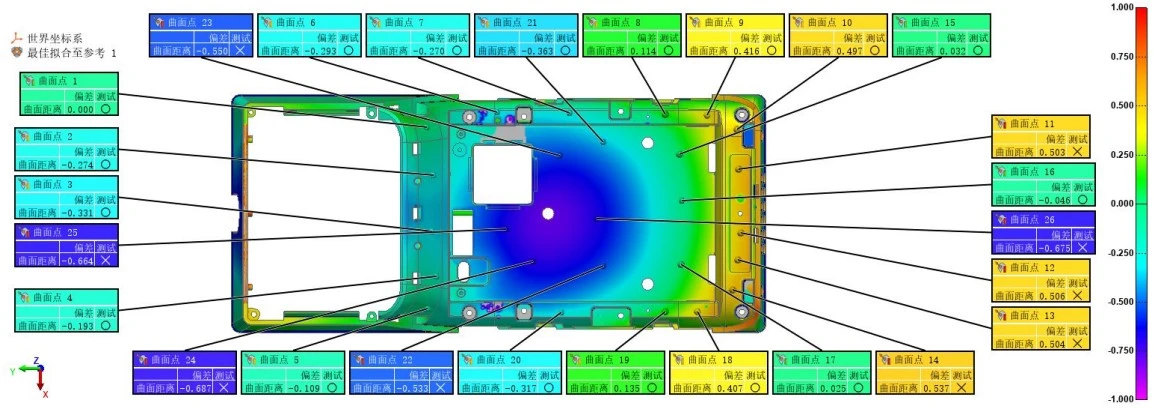
Deviation Analysis: The majority of the reference plane falls within an acceptable deviation range, indicating stable molding of this surface. Deviations are concentrated on the large, flat central section of the housing, manifesting as localized negative deviations (depressions) and positive deviations (protrusions)—a pattern characteristic of shrinkage and warpage. Data points were collected from screw bosses, corners, and edge clips, revealing molding-related deformation within the bent cavity sections.
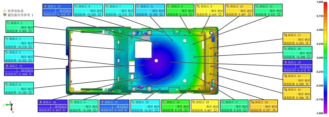
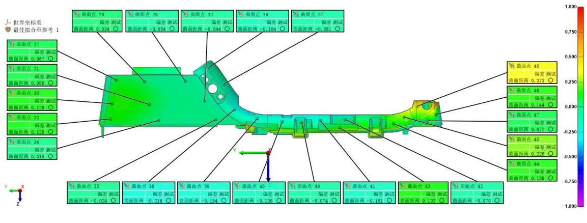
Causes and Process Implications: Significant variations in wall thickness, uneven cooling shrinkage across large flat surfaces, and stress concentrations at transitions—such as where screw bosses or corners connect to walls of varying thicknesses—lead to the formation of sink marks and warpage. The contour plots (heat maps) reveal the locations, directions, and magnitudes of these deformations, providing a basis for mold compensation and the adjustment of injection molding parameters to effectively mitigate warpage and sink marks.
III. Value of Full-Surface 3D Inspection
The examples above demonstrate that stationary blue-light 3D scanning—offering micron-level precision—can provide a comprehensive view of the entire geometry of small, precision-molded plastic parts. Its value extends far beyond the assessment of individual dimensional points.
1. Complete reconstruction of complex, intricate, and deep-cavity features. Non-contact data acquisition ensures that thin-walled plastic parts remain free from scratches or deformation caused by physical pressure. By utilizing a rotary table for multi-angle scanning, features such as grooves, locating pins, screw bosses, reinforcing ribs, and deep cavities are fully reconstructed without any loss of detail.
2. Visualization of full-surface deviations for intuitive defect localization. A color-coded deviation map provides an immediate overview of the part’s dimensional status. The locations and magnitudes of excess thickness, depressions, or warpage are clearly visible, eliminating the need to speculate on the root causes of assembly failures. A single scan enables the analysis of hole positions, pin locations, curved surfaces, and geometric tolerances, significantly streamlining the inspection process compared to point-by-point measurement.
3. Empirical data to guide mold correction and process optimization. Deviation results serve as more than just a pass/fail (OK/NG) indicator; they provide a data-driven basis for mold compensation (adjusting the mold) and fine-tuning parameters such as material temperature, holding pressure, and cooling time—ultimately shortening the iterative mold-testing cycle.
4. Support for batch-level quality trend management. By comparing multiple production batches, manufacturers can analyze overall deformation trends, identify process fluctuations, and track dimensional drift resulting from mold wear. This shifts quality assessment from focusing on a few critical points to evaluating the entire surface.
IV. Case Summary
Practical testing demonstrates that the XTOM-12M—a four-camera, stationary blue-light 3D scanner—effectively captures 3D data for precision injection-molded parts. For the first workpiece, fine features such as ribs and grooves were fully captured; for the second, deep cavities, holes, pillars, and complex bent geometries were also successfully scanned, with mesh quality meeting all inspection requirements.
Comparison against CAD models revealed that the first workpiece was generally well-molded, with deviations concentrated primarily on thin-walled clips and the part’s edges. The second workpiece exhibited localized depressions and warpage—typical of shrinkage during the injection molding process—with the reference datum remaining stable; the primary areas of deformation were identified on large flat surfaces and at transitions between thick and thin sections. A full-surface heat map (deviation map) provides a comprehensive visualization of these distributed deformations, offering a more complete assessment of molding quality than single-point sampling.
The XTOM-12M stationary blue-light 3D scanner is well-suited for full-surface 3D inspection of plastic housings and small, precision-molded components. It not only facilitates quality assessment of finished parts but also generates quantitative deviation data, providing essential insights for injection molding trials, mold adjustments, and process optimization.