Precision die-cast parts often feature complex structures, including deep cavities, recesses, numerous assembly holes, and a dense arrangement of bosses and ribs. During the high-temperature filling and subsequent cooling and solidification processes, these components are prone to various defects, such as overall warpage, uneven reference surfaces, hole-position deviations, and localized depressions or bulges.
Traditional inspection methods rely on discrete-point measurements; however, deep cavities and concealed ribs or grooves often become "blind spots" that cannot be effectively measured. This frequently leads to scenarios where individual inspection points appear to be within tolerance, yet the part still encounters interference or improper gaps during actual assembly.
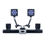
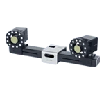
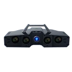
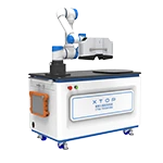
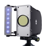
To address the challenges of inspecting complex die-cast geometries, the XTOP3D XTOM blue-light 3D scanner utilizes non-contact, micron-level area scanning. It captures comprehensive 3D data across the entire surface of a casting, effectively overcoming the limitations of traditional inspection techniques and providing a practical quality control solution for the precision die-casting industry.
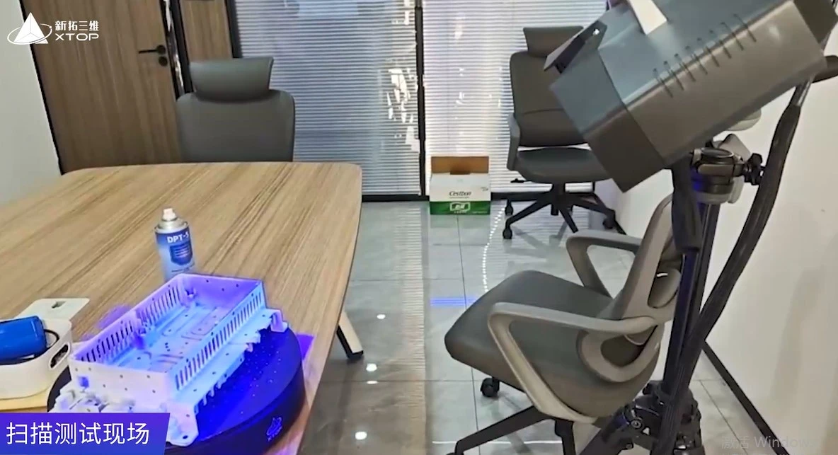
I. Inspection Requirements for U-Shaped Precision Die-Cast Parts
The workpiece is a U-shaped, deep-cavity precision die-cast part. Inspection focuses on critical areas, including assembly datum surfaces, the interior of the U-shaped deep cavity, mounting holes, and thin-walled bosses. Key requirements include:
1. Evaluating the flatness and overall warpage/deformation of the assembly datum surfaces across the entire area;
2. Measuring the spacing between mounting holes and the positional deviation of these holes;
3. Identifying molding defects—such as depressions or protrusions—within the deep cavity and on the thin-walled bosses;
4. Generating quantitative 3D inspection data to support mold rectification and the fine-tuning of die-casting process parameters, while producing traceable inspection reports.
II. 3D Scanning and Inspection Process
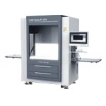
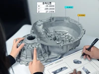
Non-contact inspection is performed using the XTOM blue-light 3D scanner, which utilizes blue-light structured-light imaging in conjunction with a motorized rotary table to capture data from multiple perspectives.
By scanning the casting from various angles—covering its external surfaces, deep internal cavities, holes, and protrusions—a high-precision 3D mesh model is generated. This scanned model is then aligned and compared against the CAD digital model to conduct a full-surface tolerance analysis, resulting in a comprehensive 3D dimensional deviation inspection report.
III. Inspection Results for U-Shaped Precision Die-Cast Parts
1. 3D Scanned Model of the Cast Part
Multi-angle 3D scanning and reconstruction are used to generate a complete 3D model of the die-cast part, accurately capturing all geometric features—such as deep cavities, bosses, and mounting holes—for subsequent digital model comparison and tolerance measurement.
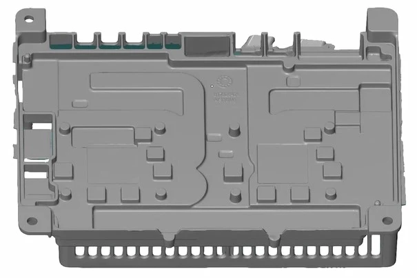
3D Scanned Digital Model of a Die-Cast Part

Scanning results for small-scale markings on castings
2. Results of Full-Field Deviation Inspection for Die-Cast Parts
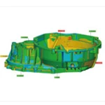
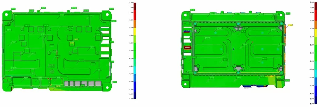
3D Full-Field Deviation Color Map (Front and Back Sides)
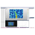
The dimensions of the main body of the casting largely conform to the design specifications; however, localized deviations—indicated by color-coded anomalies—appear at the corners of the deep U-shaped cavity, on the mounting bosses, and along the side walls. These suggest deformation patterns such as warping or bulging at the corners, and shrinkage or indentation at the base of the deep cavity.
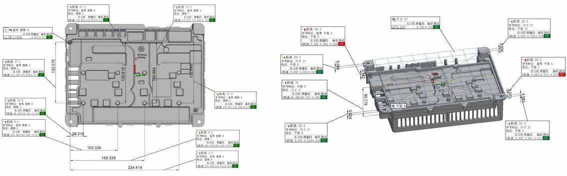
Analysis of Flatness and Geometric Dimensioning and Tolerancing (GD&T)
A GD&T analysis was conducted on the assembly datum surfaces and key features. The datum plane exhibits excessive warpage, characterized by an overall deformation pattern where both sides curve upward while the center remains slightly concave—a result of the release of residual stress during the die-casting cooling process. Additionally, certain position and distance tolerances were found to be out of specification.
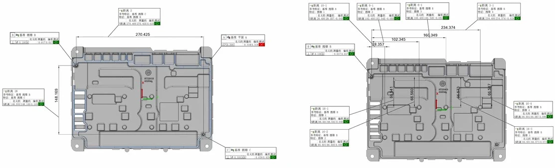
Analysis of Hole Position Tolerance and Inter-hole Spacing
A 3D inspection of the mounting holes in the casting was conducted to evaluate their positional tolerances and the distances between them. The deviations in hole positions and the actual measured values for diagonal inter-hole spacings were quantified. Certain measured values for hole positions and spacings showed deviations; these inspection data provide a quantitative basis for making corrections to the mold inserts used for forming the holes.
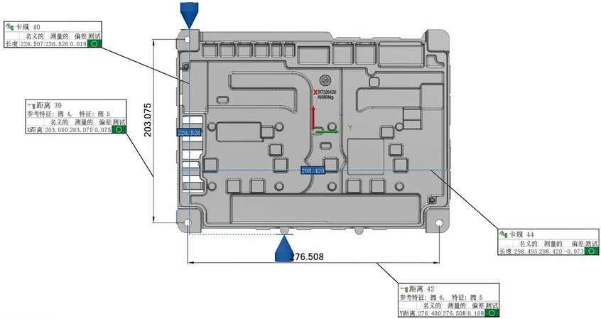
Verification of Critical Dimensions and Cross-Sections
Analyze key cross-sections to verify thin-wall thickness and check for warpage or irregularities. Simultaneously, perform actual measurements of critical control dimensions—such as those checked via gauges and the spacing between specific features—to provide quantifiable, verifiable data for mold rectification.
IV. Value of Inspection Results
1. Full-Surface Quality Evaluation: By capturing a comprehensive point cloud of the entire casting, overall warpage and deformation can be visualized. This resolves the common quality-assessment dilemma where individual measurement points may appear within tolerance, yet the part fails during assembly.
2. Shortened New Product Development Cycle: Analyzing the location, direction, and magnitude of deviations provides data-driven insights to optimize cooling channels, die-casting process parameters, and gating/riser systems. It also facilitates the adjustment of hole positions and inserts, thereby reducing the number of trial-run iterations.
3. Ensured Batch Consistency: Scanning the first article allows for the early identification of quality risks, preventing large-scale scrap or the need for extensive rework. During mass production, periodic sampling can be used to monitor mold wear—a capability well-suited for high-mix, low-volume die-casting manufacturing.
4. Standardized Quality Criteria: Highly intuitive color-coded deviation maps allow for the rapid assessment of a part’s deformation status, providing an objective, digital basis for the incoming inspection and acceptance of components.
V. Case Summary
For precision die-cast parts with deep U-shaped cavities, XTOM’s blue-light 3D scanning technology overcomes the limitations of traditional inspection methods by offering non-contact, full-field measurement at the micron level. Through the use of visualized color-coded deviation maps and quantitative GD&T (Geometric Dimensioning and Tolerancing) analysis, the system precisely identifies issues such as warpage, shrinkage, and hole-position offsets. It generates inspection data that can be directly applied to process optimization—covering the entire lifecycle from initial mold trials to quality sampling during mass production—thereby enabling die-casting manufacturers to implement proactive quality control, reduce costs, and enhance efficiency.