Abstract
To address the issue where vibrational conditions introduce additional displacements into Digital Image Correlation (DIC) measurements—thereby degrading measurement accuracy—the XTOP3D XTDIC 3D-DIC measurement system employs a vibration-error-suppression algorithm based on dynamic extrinsic parameter correction using rigid-body points. This approach was applied to test fixed-value Z-axis displacements on a 3D printer platform, enabling the evaluation of displacement accuracy and lateral coupling motion. Consequently, the measurement stability of the 3D-DIC system is enhanced under complex vibrational conditions.
I. Test Background
In FDM 3D printers, the Z-axis feed accuracy of the build platform is a primary determinant of print quality. During operation, the 3D printer generates vibrations within its own frame; these vibrations manifest as rigid-body disturbances that are superimposed onto the measurement results.
Conventional static-parameter 3D-DIC relies on a one-time calibration of the stereo-vision system performed prior to testing, with the parameters remaining fixed throughout the process. When the printer frame vibrates, the reference speckle pattern attached to the frame undergoes rigid-body motion. A static calibration model cannot distinguish between the actual displacement of the build platform and the rigid-body displacement caused by the vibration of the printer frame, which leads to distorted measurement results.
To address this, XTOP3D has developed a 3D-DIC vibration-error suppression method based on dynamic extrinsic parameter correction using rigid-body reference points. By utilizing fixed reference points on the printer frame, the system calculates the frame’s overall rigid-body motion in real time. This allows for the dynamic adjustment of the computational model, effectively filtering out the Z-axis rigid-body displacement introduced by frame vibrations. By isolating these frame-induced disturbances from the actual motion of the build platform, the method produces precise 3D displacement time-series data, meeting the requirements for high-accuracy displacement measurement under complex vibration conditions.
II. Experimental Setup
1. Experimental Subject
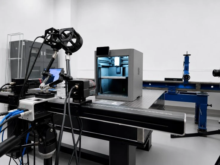
A commercial FDM 3D printer, with its Z-axis platform controlled to perform incremental movements (jogging) by set values, simulating the actual feed conditions of the equipment. Throughout the experiment, vibrations from the 3D printer’s frame are present.
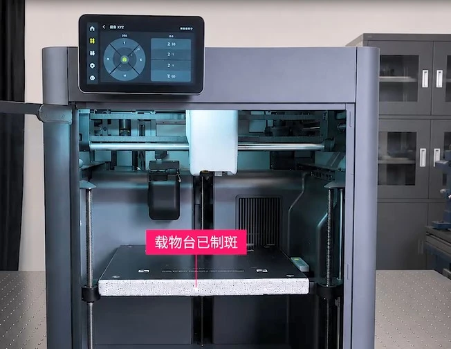
Preparation of Speckle Patterns on 3D Printer Build Platforms
2. 3D-DIC Testing System
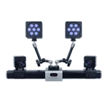
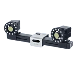
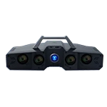
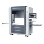
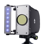
The XTDIC 3D Digital Image Correlation (DIC) measurement system features a 12-megapixel camera and a 200 mm field of view. It is equipped with a module for the dynamic correction of rigid-body motion based on reference points.
Correction Principle: By selecting stationary rigid-body reference points within the field of view, the system calculates the overall rigid-body displacement of the 3D printer frame in real time. This data is used to dynamically adjust the computational model, effectively isolating and removing the rigid-body displacement caused by frame vibrations from the measurement results, thereby isolating the true motion data of the specimen stage.
3. Preparation of Speckle Patterns on Specimens
A random black-and-white speckle pattern is applied to the surface of the specimen stage to facilitate the calculation of its displacement field. Additionally, reference speckle patterns are placed on the side walls of the 3D printer’s fixed frame; these are used to calculate and subsequently subtract the rigid-body vibrational displacement of the printer frame itself.
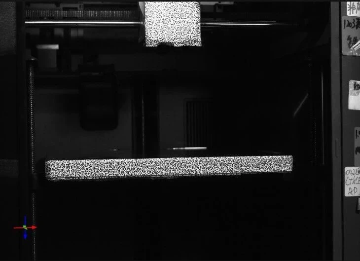
Speckle patterns on the specimen stage and the side walls of the mounting frame
4. Experimental Procedure and Control Setup
1) Perform the initial calibration of the binocular camera system, ensuring the field of view covers both the specimen stage and the reference region on the rigid-body frame; select an initial static frame as the baseline for calculations.
2) Establish two comparative calculation modes: a control group using conventional 3D-DIC with static extrinsic parameters, and an experimental group using 3D-DIC with dynamic extrinsic parameter correction (based on rigid-body reference points). Compare the measurement results obtained under vibrational conditions.
III. Experimental Results and Data Analysis
1. Z-axis Fixed-value Displacement: Quantitative Comparison of Vibration Error Suppression in the Framework
-
Experimental group (with dynamic extrinsic parameter correction for rigid-body points enabled, effectively filtering out vibrations from the 3D printer frame): actual Z-axis displacement of the stage = -9.9770 mm;
-
Control group (using conventional static extrinsic parameter 3D-DIC, without filtering out frame vibrations): measured Z-axis displacement = -9.9601 mm;
-
Additional displacement perturbation introduced by the 3D printer frame vibration: 0.0012 mm. The remaining discrepancy arises from factors such as initial point cloud matching and computational noise.
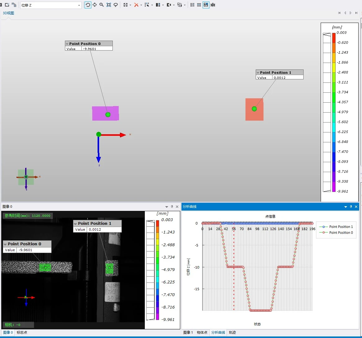
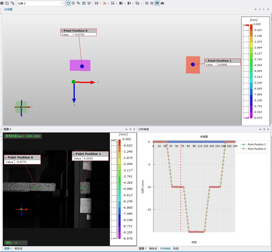
Z-direction results (rigid-body displacement not removed) & Z-direction results (rigid-body displacement removed)
In a traditional static external-parameter DIC processing mode, frame vibrations are factored into the measured displacement, leading to offsets in the measurement readings.
By enabling the dynamic external-parameter correction algorithm for rigid-body points, the Z-axis rigid-body displacement component—caused by frame vibrations—is filtered out. This effectively eliminates interference from the equipment's own frame vibrations, allowing for the recovery of the true, set-value displacement of the specimen stage.
2. Discrimination of X/Y Lateral Coupling/Crosstalk
Due to rail clearances and assembly tolerances, the Z-axis movement of the build platform induces lateral displacement in the X and Y directions; as these errors accumulate layer by layer, they result in layer misalignment during the printing process.
In the control group, minor vibrations in the printer frame along the X and Y axes contaminate the measurement data, making it difficult to distinguish whether a signal originates from frame oscillation or the actual lateral motion of the build platform.
In the experimental group, a dynamic extrinsic parameter correction for rigid-body motion is applied. By subtracting the overall rigid-body motion of the frame, the system can accurately isolate the intrinsic lateral coupled motion of the build platform, enabling the identification of multi-dimensional motion errors.
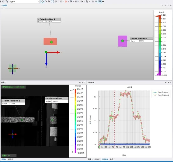
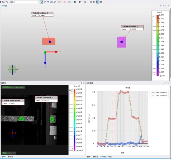
Comparison of X-direction displacements
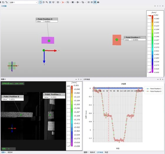
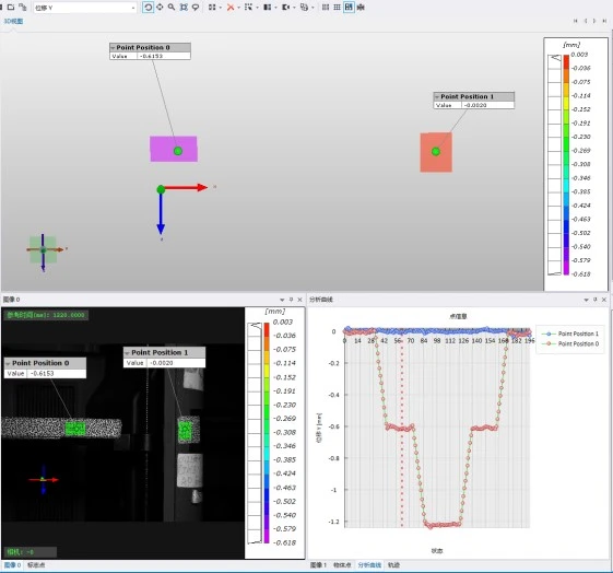
Comparison of Y-axis displacement
3. Evaluation of Dynamic Motion Characteristics
Based on the displacement-time profile, two key performance indicators can be simultaneously derived:
1) Set-point displacement accuracy: The deviation between the actual final displacement and the commanded displacement.
2) Motion stability: Including initial motion shock, feed jitter, and oscillations (rebound/vibration) upon stopping.
Only by filtering out the rigid-body vibration of the printer frame as a whole can the jitter observed in the displacement-time profile be considered representative of the stage’s true dynamic behavior.
IV. Experimental Conclusions
The operation of a 3D printer’s motors induces micron-level rigid-body vibrations in the machine’s frame. Conventional 3D Digital Image Correlation (3D-DIC) with static extrinsic parameters cannot distinguish between these frame-induced rigid-body vibrations and the actual motion of the build platform, leading to additional displacement errors in the measurement results.
In this study, the XTOP3D XTDIC 3D-DIC measurement system was employed to conduct displacement accuracy experiments on the build platform, utilizing an algorithm that suppresses vibration-induced errors through dynamic extrinsic parameter correction based on rigid-body reference points. The experiments demonstrated that vibrations in the printer frame introduce an additional Z-axis displacement disturbance of 0.0012 mm. The proposed method successfully isolates the true 3D displacement of the build platform, enabling the assessment of displacement accuracy, lateral coupling motion, and dynamic stability.
This approach validates the practical engineering applicability of the dynamic extrinsic parameter correction method for 3D-DIC measurements in vibration-prone environments. It provides a new technical pathway for extending high-precision 3D-DIC measurement technology from controlled laboratory settings to complex, real-world engineering environments.