Challenge: Difficulties in Traditional Measuring of Complex Workpieces
In manufacturing and R&D, the loss of original drawings and digital models is a common issue, particularly with legacy equipment, outsourced components, and imported spare parts that often lack accompanying design documentation. Consequently, enterprises must rely on physical parts for replication and iterative redesign, making the rapid generation of editable 3D models and engineering drawings a critical success factor.
Traditional methods capture only isolated dimensions, relying on manual estimation for complex features like chamfers, counterbores, and curved surfaces; this approach is time-consuming, prone to error, and fails to meet the ±0.03mm precision standards required for assembly. In contrast, the combination of full-field point cloud acquisition via 3D scanning and reverse modeling to generate parametric solids has emerged as the optimal solution for reverse engineering in the absence of original drawings.
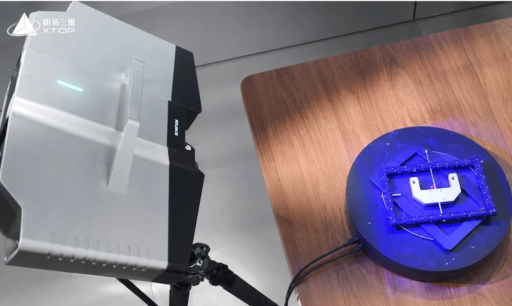
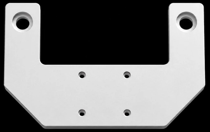
The workpiece in this case study is a U-shaped aluminum alloy connecting plate featuring counterbores, small locating holes, inclined surfaces, and internal arcs. Given the stringent assembly tolerances, the enterprise utilized blue-light 3D scanning to capture comprehensive 3D data in a single workflow, generating parametric models suitable for machining, simulation, and archiving.
I. Key Pain Points of Traditional Reverse Modeling
Traditional manual measuring tools capture only limited linear dimensions, suffer from significant cumulative error, require lengthy modeling times, and risk scratching the precision-finished surfaces of aluminum alloys. Coordinate Measuring Machines (CMMs) using single-point probing are inefficient; they face measurement blind spots in narrow grooves and small holes, while rigid probes carry the risk of scratching reference surfaces and ruining workpieces.
Neither traditional method balances data integrity, modeling accuracy, and delivery efficiency, making it difficult to meet the demands for rapid replication and iterative development of precision parts. The solution involves using the XTOP3D XTOM blue-light 3D scanner paired with a motorized rotary table to perform high-precision reverse modeling without the need for reference markers.
II. Solution: XTOM High-Precision Blue Light 3D Scanning
The XTOP3D XTOM series comprises industrial-grade 3D scanners designed for industrial inspection and reverse engineering. When paired with reverse modeling tools, the system enables a complete workflow—from point cloud data acquisition to the output of parametric STP models. It is suitable for most precision manufacturing reverse engineering scenarios and delivers outstanding performance in product design, optimization, and improvement.
Key Technical Highlights
1. Marker-free Scanning: Leveraging global coded reference points integrated into the scanning framework, the system automatically aligns data from multiple perspectives. This eliminates the need to manually apply markers to the workpiece and prevents markers from obscuring small holes or chamfers.
2. High-Density, Non-Contact Global Acquisition: The system generates dense point clouds comprising millions of points in a single pass, fully capturing intricate features—such as flat surfaces, counterbores, small holes, inclined planes, and internal arcs—without any measurement blind spots.
3. Automated Rotary Acquisition: The workpiece is mounted on a rotary table that rotates automatically at a constant speed (360°). Synchronous multi-angle data acquisition ensures the entire visible geometry of the part is captured in a single scan, eliminating data gaps.
III. Step-by-Step Reverse Engineering & 3D CAD Reconstruction Process
Step 1: 3D Data Acquisition of the Workpiece
Secure the workpiece steadily within the rotary platform frame and initiate the 3D scan after the equipment setup and calibration are complete. The rotary platform rotates at a constant speed while a blue light fringe pattern is continuously projected onto the workpiece surface; dual cameras synchronously capture the pattern deformation, and the software automatically stitches data from all viewing angles based on the global features of the frame.
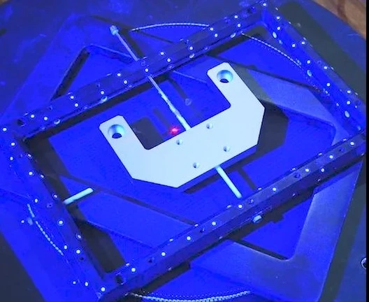
On-site blue-light 3D scanning & blue-light projection data acquisition for marker-free workpieces
Step 2: Point cloud processing and generation of high-quality STL mesh models
Raw scanned point cloud data is imported into the dedicated processing software, where the system automatically performs noise reduction, hole filling, and mesh smoothing and optimization. This generates a triangular mesh STL file that faithfully reproduces—at a 1:1 scale—all external geometries, hole locations, chamfers, and arc structures of the part.
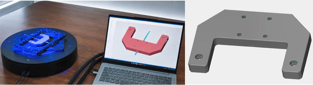
Real-time visualization of scan data & STL mesh models
Step 3: Reverse Feature Decomposition and Parametric Modeling
Unlike traditional methods that rely on a limited set of dimensions for drafting from scratch, blue-light 3D scanning provides a comprehensive, full-field mesh. Modeling is performed by extracting geometric features from the mesh to reconstruct a fully parametric solid model:
1. Automatically fit reference planes and axes to establish a unified global coordinate system for the part;
2. Extract all geometric parameters—such as wall thickness, edge radii (fillets), four small locating holes, countersunk mounting holes at both ends, and 45° chamfers—with a single click;
3. Reconstruct an editable solid model using standard feature commands (e.g., extrude, hole, fillet, cut); dimensional parameters can be freely modified to accommodate product iteration and optimization.
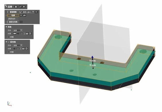
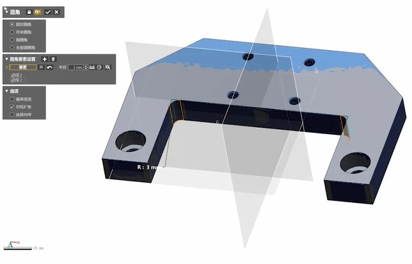
Thickness feature extraction & fillet parameter fitting
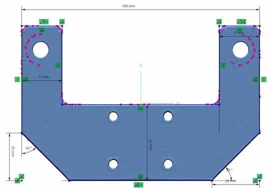
2D dimension extraction
Step 4: Model Verification and Standard CAD File Output
Once the parametric CAD model is reconstructed, a global 3D deviation analysis against the original scan mesh is performed to control overall dimensional deviation and ensure compliance with precision assembly tolerances. Following dimensional annotation and geometric dimensioning and tolerancing (GD&T) verification, the 3D model is exported in universal industrial formats (STEP, IGS), alongside a complete set of 2D manufacturing engineering drawings.
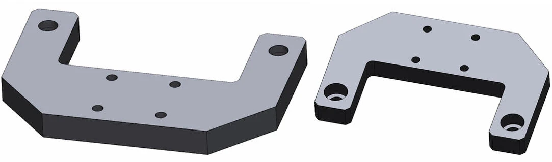
Final Solid CAD Model 1 & Final Solid CAD Model 2
IV. Key Benefits of Optical 3D Measurement for Reverse Engineering
1. Enhanced Reverse Modeling Efficiency
Traditional manual measurement and CMM-based point-data modeling involve long lead times. In contrast, the end-to-end blue-light scanning reverse engineering workflow (scanning, point cloud processing, and parametric modeling) significantly boosts efficiency, rapidly facilitating component redesigns and the emergency supply of spare parts.
2. Overcoming Accuracy Limitations of Traditional Modeling
Traditional modeling based on discrete data relies on manual estimation for transition surfaces, often leading to assembly interference. Blue-light scanning captures comprehensive, high-density point clouds that include all intricate machining features; the dimensional deviation between the reconstructed CAD model and the physical object is consistently controlled within ±0.02 mm. This ensures a 100% first-pass yield during CNC machining, eliminating the need for rework or scrapping.
3. Reduced Overall Costs
Parametric models can be reused for product redesigns, mold development, 3D printing validation, and digital twin archiving, enabling multi-purpose digital utilization of a single asset.
4. Versatile Application Across Various Component Scenarios
This photographic blue-light scanning solution is suitable for a wide range of small-to-medium-sized workpieces. It addresses full-lifecycle digital requirements, including the replication of legacy parts with missing blueprints, reverse analysis of competitor structures, product structural optimization, and comprehensive 3D dimensional quality inspection.
V. Case Summary
Traditional methods for reverse engineering components lacking blueprints suffer from inherent limitations, such as incomplete data, poor accuracy, long turnaround times, and the risk of damaging the workpiece. The XTOM blue-light 3D scanner revolutionizes the conventional "modeling from scratch" workflow by establishing a highly efficient reverse engineering pipeline that transforms physical objects into complete 3D meshes and, subsequently, into editable parametric CAD models.
Compared to traditional techniques, this solution delivers significant improvements in data completeness, modeling accuracy, and project delivery times. It serves as a standardized, high-efficiency solution for reverse engineering, digital archiving, and rapid new product development within the precision manufacturing sector.





















