In wind tunnel testing in the aerospace industry, analyzing the model's actual attitude angles and the dynamic deformation data of components is crucial for verifying simulation results and optimizing the aircraft's aerodynamic shape. Traditional contact measurements can interfere with the airflow inside the wind tunnel, making it difficult to complete tests under complex conditions such as high-speed rotors.
Digital image correlation (DIC) measurement technology is a non-contact optical measurement method that can simultaneously calculate the pitch, yaw, and roll attitude angles of a model, while also acquiring the three-dimensional deformation of components. It is the mainstream testing solution for wind tunnel testing.
I. Principle of Wind Tunnel DIC Attitude Angle Measurement
The wind tunnel test vehicle model has three core attitude angles: pitch, yaw, and roll, which are used to describe the model's deflection state in the air. DIC optical measurement technology relies on cameras to identify marked points/speckles on the model, establish the conversion relationship between the real-world coordinate system and the vehicle model's own coordinate system, and calculate the three angles.
1. Pitch Angle: This can be simply understood as the angle at which an aircraft "raises its head" or "lowers its nose." Using the horizontal plane as a reference, the angle formed between the aircraft's longitudinal axis and the horizontal plane when it tilts up or down is the pitch angle. A pitch angle is positive, and a nose-down angle is negative.
2. Yaw Angle: Equivalent to the aircraft's "nose yaw" to the left or right. Ignoring nose-up and nose-down, only consider the direction of rotation on the horizontal plane. Projecting the aircraft's axis onto the horizontal plane, the angle between this projection line and the world coordinate horizontal reference axis is the yaw angle, reflecting the magnitude of the model's horizontal yaw to the left or right.
3. Roll angle: This is the angle at which an aircraft rolls or tilts to the side. It's like an airplane's wing tilting up on one side and down on the other, causing it to flip sideways. The roll angle is the angle between the aircraft's forward axis and the vertical plane, where the aircraft's plane twists relative to the vertical plane.
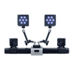
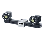
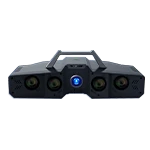
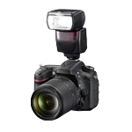
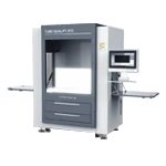
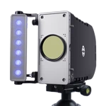
The Xintuo 3D DIC measurement system captures feature points on the model surface using a camera, maps the model's own coordinate system to the world coordinate system of the wind tunnel test, and directly outputs real-time pitch, yaw, and roll angle values.
For high-speed rotating components such as propellers, high-altitude overhead photography and low-exposure imaging are used, combined with an improved phase-locked loop to reduce the frequency of the fan blades for imaging, thus solving the problem of blurry imaging of high-speed rotating objects. At the same time, attitude and component deformation are collected synchronously.
II. Camera Vibration Suppression Technology under Complex Wind Tunnel Conditions
During wind tunnel testing, strong airflow impacts and equipment resonance can cause irregular shaking of the measuring camera, directly altering its external parameters and leading to errors in attitude angle and deformation measurement. The DIC measurement technology solution addresses vibration interference through a three-layer logic approach: hardware structural reinforcement, software algorithm correction, and a conjugate detection model.
Hardware vibration-resistant structure design: The camera mounting bracket is made of high-strength aluminum alloy or carbon fiber to improve the rigidity of the bracket structure; a customized camera vibration damping device is provided to reduce the mechanical disturbance caused by airflow impact.
Software dynamic positioning function: Marking points are attached to the surface of a completely stationary rigid component within the wind tunnel test section as spatial references. Throughout the test, the software continuously identifies these fixed marking points and performs real-time camera position calibration to compensate for measurement deviations caused by camera shake.
Dynamic correction of extrinsic parameters for camera conjugate detection model: During the experiment, the camera group will be displaced by the swing of the vertical tail, and the intersection measurement relies on accurate camera extrinsic parameters. Each camera group is equipped with a dedicated camera for dynamic positioning, which collects the marker points of the reference area on the back of the camera. Based on the spatial rear intersection theory, the absolute extrinsic parameters of the entire camera group are dynamically updated to ensure the accuracy of multi-camera intersection measurement and adapt to distributed multi-camera testing conditions.
III. DIC Phase-Locked Loop Function, Adapted for High-Speed Motion Testing Scenarios
For wind tunnel rotor high-speed rotation and component high-frequency vibration conditions, the system is equipped with an optimized external trigger phase-locked loop function, which is the core capability of high-speed dynamic testing.
Implementation principle: The DIC software reads the motion frequency of the object under test in real time, locks the first frame image acquisition position uniformly, ensures that multiple acquisitions start from the same phase position of the moving object, and displays the acquisition frame rate in real time.
Ultra-high speed motion scenarios: With a high frame rate camera and phase-locked loop function, it can track the motion trajectory of moving objects at a maximum speed of 25m/s at an object distance of 8m, meeting the dynamic testing requirements of propellers and rotors.
Strong shaking coupling scenario: suitable for vibration testing of large components. When the entire measuring equipment vibrates along with the test component, the phase-locked loop combined with the dynamic positioning algorithm is used to suppress data distortion caused by the overall shaking.
IV. The Application Value of DIC Technology in Wind Tunnel Testing
Traditional strain gauges and single-point displacement sensors are contact-based measurements. Attaching sensors will change the local flow field of the model. At the same time, the number of measurement points is limited, making it difficult to simultaneously obtain attitude angles and overall deformation.
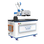
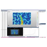
The Xintuo 3D non-contact DIC measurement system does not require the placement of contact sensors on the surface of the model under test, and does not interfere with the aerodynamic flow field. It can output three-dimensional attitude angles and full-field displacement deformation data in a single test. It is widely used for rotor blade deformation monitoring, aeroelasticity research of aircraft models, and CFD simulation result benchmarking, which helps the research and development iteration of aviation wind tunnel tests.
User FAQs
Q1: The wind tunnel environment is subject to large vibrations. Will the attitude angle measured by DIC have a large error?
A: No. On the one hand, the hardware uses high-rigidity brackets and customized vibration reduction devices to weaken mechanical vibration; on the other hand, it relies on wind tunnel static position markers, combined with the camera conjugate detection model, to dynamically refresh the camera's external parameters, offsetting the measurement deviation caused by camera shaking, and ensuring the reliability of attitude angle and deformation measurement results.
Q2: Can DIC technology be used to measure high-speed rotating propellers and rotors inside wind tunnels?
A: Yes. Relying on the phase-locked loop frequency reduction acquisition function combined with short-exposure shooting, it locks onto rotating objects for fixed-phase imaging. Under an object distance of 8 meters, it can track moving objects with a maximum speed of 25 m/s, and is suitable for dynamic testing of rotors and propellers.
Q3: What is the difference in the measurement range of DIC between closed and open wind tunnels?
A: The maximum measurement depth for the closed-circuit test is 2.5m, and the maximum measurement distance is 5m; for the open-circuit test, the maximum measurement plane is 5.0×5.0m, and the maximum object distance can reach 8m. The selection of hardware configuration needs to be determined in conjunction with the size of the wind tunnel test section and the size of the model being tested.
Q4: How many cameras are needed to conduct an attitude angle + 3D deformation wind tunnel test?
A: The basic requirements for 3D attitude angle and deformation measurement are binocular dual cameras; for full surface measurement of large-size models, it can be expanded to 6 cameras. The system supports cascading control boxes to ensure the stability of synchronous acquisition by multiple cameras.
Q5: What are the differences in accuracy and application between marker point measurement and digital speckle measurement?
A: The accuracy of single-point independent measurement of marker points is ≤0.2mm, which is suitable for calculating the model attitude angle; the accuracy of digital speckle full-field displacement measurement is ≤0.5pixel, which is mainly used to obtain the complete deformation field of the component; the two methods can be used together in actual testing.
Application scenarios: High-altitude overhead photography of aircraft propellers, using low exposure and an improved phase-locked loop (PLL) to reduce the frequency of the propeller blade image. Combined with a coordinate transformation device, it is used for attitude angle measurement and deformation measurement of model components in wind tunnel tests.