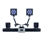
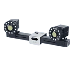
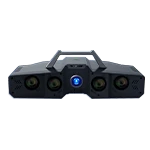
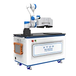
Rotorcraft wind tunnel testing is a core ground-based testing method for studying the aerodynamic characteristics, aeroelasticity, and structural dynamics of helicopters and large unmanned aerial vehicles. The flow field interference mechanisms of open and closed wind tunnels differ, posing different requirements for dynamic measurement systems. Traditional contact sensing is difficult to handle both types of operating conditions.
The following section introduces the engineering application of DIC technology in open/closed wind tunnel rotor wind tunnel tests from four aspects: wind tunnel operating conditions, DIC measurement technology adaptation logic, core measurement data, and factors affecting accuracy.
I. Characteristics of open/closed wind tunnel operating conditions?
Open-face wind tunnel : The test section is a free jet with extremely low wall blockage effect and no solid wall boundary layer compression interference, making it suitable for rotor tests with large advance ratio and large attitude angle; the disadvantages are that the jet is easily affected by environmental disturbances, the flow field noise is high, and image acquisition is easily affected by stray light and airflow refractive index fluctuations.
Closed wind tunnel : The closed recirculation test section has low turbulence and good wind speed uniformity, and excellent test repeatability. It is often used for steady-state aerodynamic calibration, high-speed rotor flutter and stiffness testing. However, there are wall blockage and induced backwashing effects. Cavity reflection and changes in optical path refractive index are the main sources of interference in optical measurements.
II. Is DIC technology compatible with open/closed wind tunnel rotor measurement?
Non-contact measurement . Rotor blades are thin-walled, flexible components, and contact measurements can alter their local stiffness and aerodynamic shape. DIC non-contact data acquisition preserves the original mechanical boundaries of the blades, resulting in flapping/swaying/torsional responses that more closely resemble real-world wind conditions.
Global field measurement . Unlike single-point sensing, DIC technology can simultaneously obtain the displacement and rotation distribution of the entire field from the blade root to the blade tip, and capture the torsional gradient and deformation differences along the span, making it suitable for analyzing the spatial distribution of aerodynamic loads along the blade.
Balancing dynamic and accuracy requirements . In open wind tunnels with strong disturbances, DIC technology, combined with a high-speed camera and robust speckle matching algorithm, can stably track the transient motion of rotating blades; in closed wind tunnels with steady-state calibration, the binocular DIC measurement system can stably output sub-angular level rotation and micron-level displacement, meeting high-precision calibration requirements.
One calibration supports switching of operating conditions . When switching between open and closed test sections, the camera extrinsic parameter calibration results can be reused, eliminating the need for repeated adjustment of sensor points and shortening the multi-condition comparison test cycle.
III. What are the key data points for DIC measurable wind tunnel testing?
Flapping Angle Timing : The amplitude, frequency, and phase of the blade's vertical oscillation around the flapping hinge, used to evaluate flapping vibration, resonance boundary, and fatigue load in hovering/forward flight states.
Shimming Angle Timing : The forward and backward oscillation angle of the blade in the plane of rotation, used to identify shimming instability, evaluate the damping characteristics of the blade hub, and investigate dynamic load amplification under high-speed rotation.
Spanwise torsion angle distribution : The dynamic torsion angle of each blade section directly reflects the real-time change of the aerodynamic angle of attack along the spanwise direction, and is the core parameter for tunnel wall interference correction and blade aeroelastic coupling analysis.
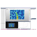
Full-field displacement and strain field : Simultaneously acquire blade spanwise and chordal deformation contour maps for analysis of structural elastic deformation, load reconstruction and aeroelastic coupling mechanism.
IV. What are the main factors affecting the accuracy of DIC rotor measurement?
Speckle quality : The size, contrast, and adhesion of the speckle particles directly determine the matching stability under high-speed rotation and large deformation. Speckle loss will cause data gaps.
DIC system calibration : The accuracy of the calibration board, the coverage of the calibration field of view, and the camera attitude determine the accuracy of 3D reconstruction; large field of view rotor measurement requires controlling the accuracy attenuation in the far field region.
Optical environment : Refractive index fluctuations caused by airflow in open wind tunnels, reflections from the inner walls of closed wind tunnels, and uneven light sources can introduce image noise, requiring the use of optical shielding and stable lighting.
Matching of acquisition parameters : The higher the rotor speed, the higher the required camera frame rate and shutter speed; insufficient shutter speed will cause motion blur, directly reducing the accuracy of angle and displacement calculation.
V. Application Summary
Open-face wind tunnels are suitable for dynamic exploration under large operating conditions, while closed-face wind tunnels are suitable for high-precision steady-state calibration. The DIC system relies on non-contact full-field optical measurement capabilities, and can be used for rotor blowing tests in both types of wind tunnels with a single device. It can simultaneously acquire flapping, oscillation, torsion, and full-field deformation data, avoiding the additional stiffness interference and measurement point limitations caused by contact measurements, and supporting refined experimental research on rotor aeroelasticity, dynamic stability, and load characteristics.
VI. User FAQs
Q1: Can DIC be used as a single system to conduct rotor tests in both open and closed wind tunnels?
A1: Yes. The DIC system can be configured to adapt to dynamic acquisition of strong disturbances in open wind tunnels and steady-state high-precision calibration in closed wind tunnels. After calibration, it can support rapid switching of operating conditions.
Q2: Will fluctuations in the refractive index of the airflow in an open wind tunnel affect the DIC results?
A2: Airflow disturbances can introduce image noise. Most of the pulsation interference can be suppressed by using high shutter speed, strong lighting, and robust correlation algorithms. Under strong disturbance conditions, it is recommended to increase repeated sampling and perform statistical averaging.
Q3: Will the blockage effect of the closed wind tunnel walls cause deviations in DIC measurements?
A3: DIC measures the actual motion response of the rotor. The cavity wall effect is reflected in the load and deformation of the blades. DIC can directly capture this response and use it for cavity wall interference quantification and test data correction.
Q4: Will high-speed rotating blades cause speckle mismatch or data loss?
A5: Motion blur and large deformation at high speeds increase the risk of lost pixels, which can be significantly improved by optimizing speckle technology, increasing frame rate, and shortening exposure time.