In wind tunnel testing of fixed-wing aircraft models, attitude angle changes, wing surface elastic deformation, and aerodynamic coupling offset are the core metrics for evaluating the aircraft's aerodynamic performance, attitude stability, and aeroelastic characteristics. Traditional single-point measurement methods cannot meet the requirements for multi-attitude, full-domain, and synchronous dynamic data acquisition of fixed-wing models.
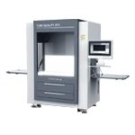
The DIC digital image correlation measurement system uses a dedicated industrial camera, stroboscopic light source, dual probes for synchronous acquisition, attitude batch sampling, and coordinate reconstruction calculation to accurately and stably solve the core motion parameters of fixed-wing models such as pitch, yaw, and roll. It is the mainstream engineering solution for wind tunnel fixed-wing dynamic measurement.
I. Hardware Configuration for Wind Tunnel Fixed-Fly DIC Measurement
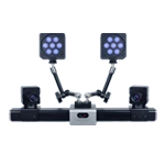
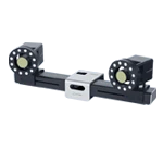
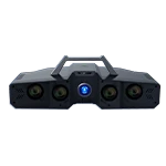
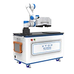
In response to the characteristics of fixed-wing models, such as large size, numerous attitude changes, significant flexible deformation of the wing surface, and strong interference from wind tunnel ambient light, the wind tunnel test adopts a standardized high-precision DIC hardware combination to ensure the accuracy and stability of synchronous data acquisition across the entire domain.
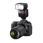
1. Acquisition Camera : Equipped with a CXP high-speed industrial camera, supporting 90fps high frame rate acquisition, it can clearly capture the attitude fine adjustment of the fixed wing model, slight wind disturbance deviation, and small elastic deformation of the wing surface without motion blur, meeting the requirements of continuous sampling of multiple attitudes.
2. Optical Lens : Standard configuration includes a 16mm fixed-focus industrial lens, covering the entire fixed-wing model fuselage and wing surface with minimal distortion and sufficient depth of field, suitable for wind tunnel wide-field and long-distance shooting conditions, ensuring consistent image clarity across the entire area.
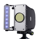
3. Supplemental Light Source : A custom-designed pulse-triggered stroboscopic light source is used, with a maximum illuminance of 10,000 LUX. Through stroboscopic synchronous triggering, stray light and airflow light and shadow disturbances in the wind tunnel environment are effectively suppressed, ensuring uniform brightness and stable contrast in images acquired for each attitude measurement.
4. Calibration Components : Equipped with a high-precision crosshair calibration plate and coordinate transformation plate, used to complete the calibration of dual-camera intrinsic and extrinsic parameters, establish a global coordinate system, and transform the wind tunnel test coordinate system, ensuring the accuracy of 3D reconstruction and motion parameter calculation.
II. Fixed-wing wind tunnel DIC measurement and control logic
The fixed-wing model requires frequent attitude adjustments and small angle step intervals, necessitating the use of a DIC measurement system with dual-probe synchronous acquisition and phase-shift trigger control mode to avoid issues such as single-view occlusion, asynchrony, and data deviation.
The DIC measurement system adopts a dual-view layout with a top main probe and a side auxiliary probe . The two probes achieve millisecond-level synchronous exposure through hardware phase shift triggering, eliminating attitude acquisition timing deviations.
The top DIC probe is responsible for capturing the vertical attitude of the fuselage and the overall deflection of the wing surface, while the side wall DIC probe is responsible for correcting the lateral offset and roll attitude. The dual-view data fusion completely solves the problems of single-sided occlusion and limited field of view in fixed-wing models.
The wind tunnel attitude test adopts a fixed-point batch sampling mechanism: for each attitude angle adjustment of the model, the system automatically and continuously acquires 20-50 high-definition sequential images , and then enters the next attitude condition after completing steady-state data sampling.
Multi-frame sampling can filter out random errors caused by wind tunnel micro-airflow disturbances and slight model jitter, ensuring that the motion parameters of each posture have high repeatability and reliability.
III. Standardized Measurement Procedures for Fixed-Fly Models using DIC
The calculation of fixed-wing motion parameters in wind tunnels relies on binocular vision 3D reconstruction technology. The entire process is standardized, feasible, and adaptable to batch tests in high- and low-speed, open/closed wind tunnels.
1. System internal and external parameter calibration : Using a high-precision calibration board, complete the distortion correction of the DIC dual camera, solve the internal and external parameters, and establish a binocular three-dimensional measurement coordinate system; match the wind tunnel test reference coordinate system through a coordinate transformation board to unify the attitude calculation reference.
2. Model marker placement : High-stability markers are pasted on key locations of the fixed-wing fuselage, wings, and tail to serve as core feature points for attitude solving, spatial positioning, and 3D reconstruction.
3. Dual-probe synchronous image acquisition : Under wind tunnel conditions, dual probes on the top and side walls synchronously acquire images of various attitude sequences, fully recording the spatial position of the model under different angles of attack and sideslip angles.
4. 3D coordinate reconstruction calculation : The system identifies the pixel coordinates of the marker points in the left and right views, reconstructs the real 3D spatial coordinates of the marker points through a binocular parallax algorithm, and generates the real-time spatial pose matrix of the model.
5. Fixed-wing motion parameter solution : Based on the three-dimensional coordinate changes of the marked points, accurately calculate the real-time changes of the model's pitch angle, yaw angle, and roll angle , and output full-domain data such as wing surface displacement, bending deformation, and elastic torsion.
IV. Key Measurement Data from DIC Output
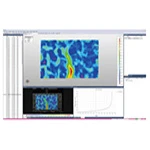
Three-dimensional displacement field of the wing surface: time sequence of spanwise and chordwise displacement of the wing, quantifying the overall bending deflection under different angles of attack and wind speeds.
Cross-sectional torsion angle distribution: The torsion angle of each cross section along the span of the wing reflects the elastic torsion induced by aerodynamic loads and is used for angle of attack correction and aeroelastic coupling analysis.
Attitude angle timing: wing pitch, roll, and yaw angles, used for model attitude monitoring and aerodynamic coefficient correction.
Full-field strain field: continuous strain distribution on the airfoil, identifying stress concentration areas, and assisting in structural strength assessment.
Vibration modes and time-frequency data: Natural frequencies, mode shapes and damping are extracted from wing flutter tests to determine the critical flutter boundary.
V. Application Summary
Wind tunnel fixed-wing DIC measurement, relying on a dedicated CXP camera, stroboscopic light source, and dual-probe synchronous triggering architecture, combined with standardized multi-attitude batch acquisition and 3D coordinate reconstruction algorithms, can obtain high-precision and stable core motion parameters of pitch, yaw, and roll of fixed-wing models, as well as full-domain deformation data.
The entire DIC measurement process fully complies with wind tunnel test engineering specifications and is adaptable to open/closed, high and low speed full-condition fixed-wing wind tunnel tests, providing a standardized and traceable digital measurement solution for aircraft attitude calibration, aerodynamic data analysis, and structural elasticity characteristic research.
FAQs
Q1: Why is a dual-probe layout the preferred solution?
A1: The top and side wall dual-view system can complement each other to block blind spots, and synchronous triggering of acquisition ensures that the attitude timing is completely consistent. It has higher accuracy and more complete attitude calculation dimensions than monocular DIC, and is suitable for fixed-wing three-axis attitude change measurement.
Q2: What is the purpose of acquiring 20-50 images for each pose?
A2: Multi-frame averaging can filter out minor disturbances in wind tunnel airflow, slight model jitter, and ambient light and shadow noise, greatly improving the stability of single-attitude data. It is the standard sampling process for wind tunnel steady-state testing.
Q3: What is the function of the stroboscopic light source?
A3: The 150W high-power pulse strobe can instantly fill in the light and freeze the attitude motion, eliminating motion blur, while isolating the wind tunnel environment from stray light interference, ensuring consistent image quality for each attitude acquisition.
Q4: What are the uses of the attitude angle data calculated by DIC?
A4: The attitude parameters reconstructed based on 3D marker points are real physical angles, with high accuracy and traceability, and can be directly used for wind tunnel aerodynamic data correction and attitude error compensation.