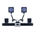
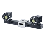
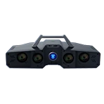
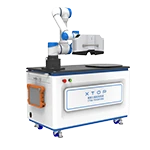
Wind tunnel testing is a core ground-based testing method for verifying the aerodynamic performance, analyzing attitude stability, and studying aeroelasticity of aircraft. Aircraft models undergo attitude deflection, structural vibration, and micro-deformation under airflow loads. Accurately acquiring various motion parameters is crucial for ensuring the reliability of aircraft design iterations and experimental data.
Contact measurements are prone to interfering with the model's flow field, have limited measurement points, and exhibit weak dynamic response, making them unsuitable for high-precision, full-range, and dynamic testing requirements. Digital image correlation (DIC) technology can efficiently and accurately acquire multi-dimensional motion parameters of aircraft models during wind tunnel testing, significantly improving data accuracy and testing efficiency.
I. Basic Environment and Test Types for Wind Tunnel Testing
Characteristics of open and closed wind tunnel environments
Wind tunnel test sections are mainly divided into two structural forms: open and closed, to adapt to different test scenarios. Open wind tunnels have no enclosed walls, resulting in less airflow obstruction and weaker boundary layer interference, making them suitable for low-speed static tests and small-amplitude model attitude tests. However, they are easily affected by ambient airflow and require higher stability from the measurement system. Closed wind tunnels provide a completely enclosed flow field environment with low turbulence, stable wind speed, and excellent flow field quality. They can meet the requirements for high-speed and ultra-high-speed steady-state and transient precision testing, making them the mainstream operating environment for high-precision calibration of aircraft.
Wind tunnel classification and applicable testing scenarios
According to Mach number (Ma), wind tunnels can cover the entire flight envelope of an aircraft for simulation testing:
1. Low-speed wind tunnel (Ma < 0.4): mainly simulates aircraft takeoff, landing, and low-altitude cruise conditions, and is used for experimental research on low-speed aerodynamic characteristics, lift enhancement devices, attitude stability, etc.
2. High-speed wind tunnel (0.4≤Ma<5): including transonic wind tunnel (0.4≤Ma<1.4) and supersonic wind tunnel (1.4≤Ma<5), widely used for transonic and supersonic aerodynamic performance testing of various aircraft.
3. Ultra-high speed wind tunnel (Ma≥5): Designed for hypersonic spacecraft, used for experimental research on aerodynamic loads, structural response and aerodynamic characteristics under extreme conditions.
II. Definition of Core Motion Parameters for Wind Tunnel Testing
Wind tunnel testing requires the accurate collection of fixed-wing attitude parameters and rotor structure motion parameters, which are the core basis for aerodynamic data analysis, model attitude correction, and flight stability assessment.
Fixed-wing aircraft attitude parameters
Pitch angle: The angle between the aircraft's axis (nose direction) and the horizontal plane. The model's pitch angle is positive, directly reflecting the aircraft's longitudinal attitude change and vertical movement characteristics.
Yaw angle: The angle between the actual heading of an aircraft and the reference heading, used to evaluate the aircraft's heading deviation and lateral stability performance.
Roll angle: The angle of rotation of the fuselage around its front and rear axes, representing changes in roll attitude, and directly affecting wing loading distribution and flight attitude balance.
Rotor model motion parameters
Flapping angle: The angle at which the rotor blades swing up and down around the flapping hinge is an important parameter for judging rotor aerodynamic vibration and load fluctuation.
Swing angle: The angle at which the blade swings back and forth in the plane of rotation, reflecting the dynamic damping of the rotor and the operational stability of the structure.
Twist angle: The twist angle of the blade's cross section, which directly determines the rotor's effective angle of attack and aerodynamic output characteristics.
III. Limitations of Traditional Wind Tunnel Measurement Methods
Traditional wind tunnel motion parameters are mostly collected using encoders, displacement sensors, and contact strain gauges, which have significant shortcomings:
Contact installation will change the original structural stiffness and flow field state of the model, introducing additional interference errors;
It only supports single-point and local measurements and cannot obtain continuous deformation and attitude distribution of the entire wing, tail, and rotor.
The response speed is insufficient under high-speed and transient conditions, making it difficult to capture high-frequency vibrations and instantaneous attitude changes, and thus failing to meet the testing standards of modern aerospace wind tunnel testing.
IV. Advantages of DIC technology measurement
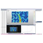
DIC (Digital Image Correlation) technology uses markers pasted on the model surface and a high-speed camera to continuously acquire images before and after the experiment. Relying on grayscale correlation matching algorithms, it accurately calculates the three-dimensional displacement, rotation, and deformation data of all markers in the field, achieving non-contact, global, and dynamic motion parameter solving.
In wind tunnel testing scenarios, DIC technology possesses four core advantages:
1. Non-contact and non-interference: No sensors need to be installed, the flow field is not disrupted, the mechanical state of the model is not changed, and the real aerodynamic motion response is reproduced.
2. Full-field measurement: Breaking through the limitations of single-point measurement, it can simultaneously acquire continuous attitude and deformation data of the fuselage, wings, tail, and rotor.
3. Full-condition compatibility: Compatible with open/closed wind tunnels, suitable for low-speed steady-state, high-speed transient, and ultra-high-speed extreme condition measurements.
4. High precision and high dynamics: It can achieve sub-angle-level angular accuracy and micron-level displacement measurement, and is suitable for high-frequency vibration and instantaneous attitude change acquisition.
V. Application of DIC technology in wind tunnel motion parameter measurement
During the experiment, by accurately calibrating the binocular vision coordinate system and the horizontal plane reference, and combining it with speckle image dynamic tracking, the full-dimensional motion parameters of fixed-wing and rotor models can be efficiently calculated.
For fixed-wing aircraft models, the DIC measurement system accurately calculates the dynamic pitch, yaw, and roll angle changes during the test by identifying the real-time spatial positions of the fuselage reference axis and the wing reference plane, thus realistically reproducing the attitude stability characteristics under different wind speeds and Mach numbers.
For the rotor model, relying on high-speed inter-frame matching capability, the dynamic position change of the blades is tracked in real time, and the flapping angle, sway angle and torsion angle are accurately solved, effectively evaluating the aerodynamic stability and structural dynamic response of the rotor under high-speed rotation.
Whether it's static attitude fine-tuning in low-speed wind tunnels or transient aerodynamic coupling, flutter response, and instantaneous attitude change tests in high-speed and ultra-high-speed wind tunnels, DIC technology can output continuous, traceable, and quantifiable full-field test data, providing reliable data support for aircraft aerodynamic optimization, structural improvement, and stability verification.
VI. Conclusion
DIC (Digital Image Correlation Technology) completely solves the pain points of traditional wind tunnel testing, such as large interference, sparse measurement points, and insufficient dynamic performance in contact measurements. It can accurately measure multi-dimensional motion parameters of aircraft models and is suitable for all types of wind tunnel testing scenarios, including open/closed tunnels, low-speed/high-speed/ultra-high-speed tunnels.
With its non-contact, full-range, high-precision, and high-dynamic technical characteristics, DIC technology effectively improves the authenticity and integrity of wind tunnel test data, providing an efficient and reliable testing solution for aerodynamic research and development, structural optimization, and digital upgrade of wind tunnel testing for aircraft.