summary
In a multi-camera DIC system, each probe's coordinate system is independent, and 3D data of the same object measured by different probes cannot be stitched together, resulting in displacement jumps and inconsistent spatial positions. Rigid positioning calibration, which involves forcibly unifying the global coordinate system through global control points, determines the spatial attitude and orientation of each camera, and reduces all probes to the same global coordinate system, is the core and key step in multi-camera DIC and multi-probe collaborative measurement.
This article explains the rigid positioning calibration principle, applicable scenarios, complete calibration steps, factors affecting calibration accuracy, and key points of system configuration, helping to understand the logic of establishing global coordinates in multi-probe DIC.
I. What is DIC rigid positioning calibration?
Multi-camera DIC probes have their own independent local coordinate system, and there is no unified reference between the probes, making it impossible to directly fuse multiple sets of measurement results into the same three-dimensional space.
Rigid positioning calibration involves using spatially distributed global control points (global points) to rigidly establish a unified global coordinate system; solving the rotation and translation relationships of each probe relative to the global coordinate system; determining the spatial orientation and position of each camera; and mapping all probe measurement results to the same global coordinate system to achieve seamless stitching and reconstruction of multi-probe data.
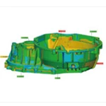
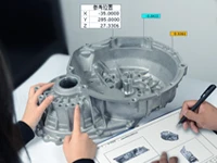
Application value: It enables simultaneous measurement of inner and outer walls, multi-view measurement of large components, and collaborative measurement of reflector probes, which is the foundation for the multi-camera DIC system to output unified three-dimensional results.
II. In which scenarios is rigid positioning calibration applicable?
For multi-probe collaborative operation, rigid positioning calibration is required in the following scenarios:
1. Multiple sets of binocular probes simultaneously observe the same large component, and the probe data are fused into a single three-dimensional coordinate system;
2. A combination of a standard probe and a reflector probe enables simultaneous three-dimensional reconstruction of the inner and outer walls;
3. Simultaneous acquisition by multiple probes, outputting a complete three-dimensional displacement and �strain field of the object from multiple angles;
4. The test distance is relatively long and the probes are distributed in different locations in space, requiring the measurement results to have a unified spatial reference.
III. Complete Execution Steps for DIC Rigid Positioning Calibration
The entire calibration process is divided into two main stages: calibration of individual probe intrinsic and extrinsic parameters → calibration of probe rigid positioning (global point).
Step 1: Calibration of internal and external parameters of a single probe (calibration plate)
For each pair of binocular cameras, the intrinsic parameters of the camera group and the relative extrinsic parameters between the two cameras in the group are solved using a standard calibration board.
Place the calibration plate within the probe's field of view and acquire images of the calibration plate from multiple angles and positions;
Determine the internal parameters of the two cameras in this group, including lens distortion, focal length, and principal point.
Solve for the relative rotation and translation between the two cameras in this group, and establish the local coordinate system of this probe itself.
Step 2: Rigid positioning calibration of a single probe (global point)
Rigid positioning is performed using a spatial global control point target, aligning all probes to the same global coordinate system.
Targets with high-precision global control points are placed in the measurement space; the target control points are distributed throughout the entire test space, and each control point is observed by at least one set of probes, with key control points being observed by multiple sets of probes simultaneously as much as possible.
All probes simultaneously acquire global point images;
The true 3D global coordinates of the control points are read, and the DIC software solves the rotation matrix and translation vector of each probe relative to the global coordinate system to determine the spatial position and orientation of each camera.
All DIC probe measurement data are converted to a unified global coordinate system to achieve the merging and reconstruction of multi-probe results.
IV. Key Factors Affecting the Accuracy of Rigid Positioning Calibration
The accuracy of rigid positioning calibration directly determines the errors in displacement and 3D coordinates after multi-camera DIC stitching, and is mainly constrained by the following factors:
· Global control point target accuracy: The number and spatial distribution of control points are crucial. Control points should cover the entire working area of the test piece as much as possible.
· Single probe basic calibration quality: It is essential to ensure that the internal and external parameters of each probe are calibrated on the calibration board first.
· Rigidity of the support system: In long-distance measurement scenarios, the anti-vibration performance of the support is particularly important.
· Global point image imaging quality: Simultaneous observation of common control points by multiple probes as much as possible to improve coordinate system transformation constraints.
· Environmental temperature drift: Temperature changes cause slight deformation of the bracket and camera base, which will change the spatial orientation of the camera and cause a shift in the rigid positioning relationship.
V. Configuration Recommendations for Rigid Positioning Calibration Implementation
First, complete the calibration of the internal and external parameters of each probe calibration plate one by one, and then perform global point rigid positioning. The order cannot be reversed.
Global control point target layout: Control points need to be scattered throughout the entire three-dimensional space occupied by the object being measured, and should not be concentrated in a small area of the plane; try to ensure that some control points are captured simultaneously by two or more probes.
After calibration, lock all probe brackets, mark them, and strictly prohibit any changes to the camera attitude during the testing process; if a collision or displacement occurs, the rigid positioning calibration must be performed again completely;
For large-scale, long-distance testing scenarios, a high-rigidity, stable bracket is selected to reduce attitude drift caused by vibration and temperature drift.
After calibration, it is recommended to conduct a verification test: select a spatial verification point, use different probes to measure the three-dimensional coordinates of the same point, verify the consistency of the results from multiple probes, and confirm the effectiveness of the rigid positioning calibration.
VI. Conclusion
DIC rigid positioning calibration is the core technical process of multi-camera DIC. It essentially relies on high-precision global control points to perform coordinate transformation on multiple independent probes, rigidly unify the global coordinate system, and determine the spatial orientation of each camera.
The complete process is divided into: calibration of internal and external parameters of single probe calibration board → rigid positioning calibration based on global points.
The calibration effect is affected by the target accuracy, control point distribution, support rigidity, and image quality; recalibration is necessary after camera displacement. Rigid positioning calibration is required to achieve multi-probe and reflector probe coordination, enabling synchronous 3D reconstruction of large components and inner and outer walls.