To address the difficulty of measuring full-field deformation in cylindrical components during welding using traditional methods, the XTOP3D XTDP 3D optical photogrammetry system was employed to measure the full-field deformation of such components under welding conditions.
To verify the feasibility of this measurement method, a welding experiment on cylindrical components was designed and conducted, and accuracy validation tests were performed using a calibration cross. The results demonstrate that the method achieves a deformation measurement accuracy of 0.020 mm/1 m, enabling the measurement of 3D full-field static deformation in cylindrical components during welding.
I. Project Background
Cylindrical components are critical parts in aerospace vehicles, marine vessels, and petrochemical machinery. Measuring and controlling welding deformation in these components has become a key challenge requiring urgent resolution in the high-end equipment manufacturing industry.
Measuring the 3D full-field deformation of cylindrical components aids in analyzing factors that influence welding deformation, revealing deformation mechanisms, predicting deformation trends, and validating numerical simulation methods. This is of great significance for eliminating residual welding stress, optimizing welding processes, and extending service life.
The XTOP3D XTDP 3D optical photogrammetry system is used to track a dense array of non-coded markers attached to the outer surface of the cylindrical component. By calculating the 3D coordinates of these markers before and after welding, the system determines the 3D full-field static deformation.
II. 3D Full-Field Static Deformation Measurement System
Components of the XTDP 3D Full-Field Static Deformation Measurement System:
High-resolution digital camera (12 megapixels or higher)
Flash unit, coded markers, non-coded markers, and scale bars
High-performance computer and measurement analysis software
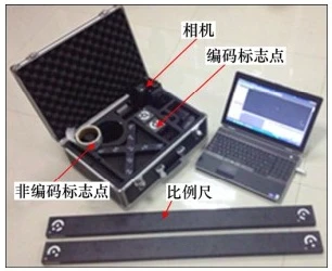
3D Full-Field Static Deformation Measurement System
III. Experimental Setup and Procedure
The experimental setup primarily consists of a welding robot and an XTDP 3D optical photogrammetry system; the welding robot performs the welding operations, while the XTDP system handles image acquisition, calculation, and analysis. Based on this setup, static deformation measurement experiments were conducted on a cylindrical component using MIG welding and laser welding, respectively.
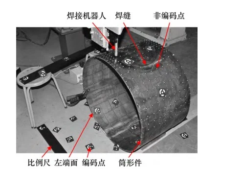
Experimental setup
To avoid difficulties in capturing full-field 3D deformation on the lower semicircle of the cylindrical component due to obstruction, the following non-coded marker placement scheme was adopted: for the upper semicircle, markers were applied to the outer cylindrical surface, with higher placement density near the weld zone; for the lower semicircle, markers were applied to the inner cylindrical surface, with lower placement density in areas further from the weld zone.
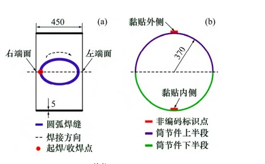
单位:mm (a) 俯视图;(b) 轴视图
Diagram showing the placement of non-coded markers on a cylindrical part
The deformation measurement process primarily involves the following steps:
1) Conducting full-field deformation measurements for laser welding using welding robots and laser welding torches.
2) Arranging an appropriate number of coded markers and two scale bars around the cylindrical component, ensuring their positions remain unchanged throughout the measurement process.
4) Using the XTDP system's DSLR camera to capture images of the undeformed cylindrical component from various spatial orientations prior to welding.
5) Capturing images of the deformed cylindrical component from various spatial orientations again after the welding process is complete.
6) Performing calculations and analysis using XTDP software to obtain the deformation measurement results.
IV. Experimental Results and Analysis
1. MIG Welding Experiment
High welding temperatures can cause localized burning and damage to some non-coding points, thereby affecting their identification and coordinate calculation; however, the use of a deep search algorithm enables successful matching and the determination of deformation magnitude, which is of great significance for analyzing the deformation mechanism in critical weld zones.
Static deformation experiment on laser-arc hybrid welding of a cylindrical component; the measurement results are shown in the figure below:
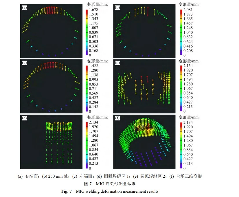
Results of MIG welding deformation measurements
2. Laser Welding Experiment
The deformation of the cylindrical component caused by laser welding is similar to that caused by MIG welding; consequently, the matching calculation for low-deformation points in the weld zone can also be achieved through a deep search method.
A laser welding experiment was conducted on the same cylindrical component at a location diametrically opposite the MIG weld zone; the measurement results are shown in the figure below:
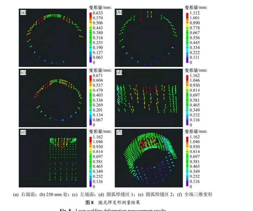
Measurement results of laser welding deformation
2. Experimental results demonstrate that the depth-first search algorithm enables successful matching of weak deformation points in the weld zone and subsequent deformation calculation, thereby achieving 3D full-field static deformation measurement of welded cylindrical parts; the measured results align with the actual deformation.
3. Accuracy Verification
To further verify the overall measurement accuracy and stability of the XTDP 3D optical photogrammetry system, an accuracy verification experiment was conducted using the commercial TRITOP system from GOM (Germany) as the measurement benchmark.
The accuracy verification experiment for the XTDP system was performed in fixed-focus mode, utilizing a dual-reference scale and a calibration cross-scale arranged at a 45° angle to each other; the results are presented in the table and figure below.
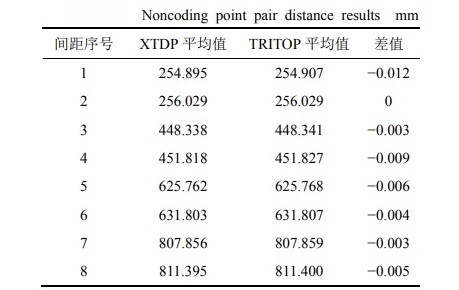
Table of Measurement Results for Non-coded Point-to-Point Spacing
As shown in the table above, the average spacing values for the two are very close; the values calculated by XTDP are generally slightly lower, and the measurement deviation is less than 0.020 mm/1 m (with a maximum deviation of −0.012 mm/1 m).
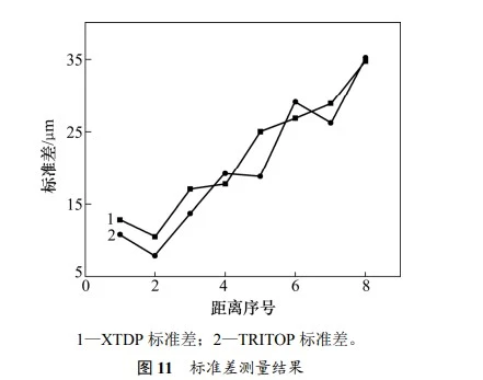
Standard deviation measurement results
As shown in the figure above, the standard deviation of the XTDP system is slightly higher than that of the TRITOP system, though the two are generally comparable; furthermore, the standard deviations of both systems increase in tandem as the measurement distance grows, effectively demonstrating the stability of the XTDP system. Consequently, the XTDP system exhibits a measurement deviation of less than 0.020 mm/m and stability comparable to the TRITOP system, with a maximum standard deviation difference of 0.007 mm. It meets the requirements for 3D full-field static deformation measurement during the welding of cylindrical components, thereby effectively validating the feasibility and stability of the XTDP system.
V. Analysis of Experimental Conclusions
1) To address the need for measuring static deformation during the welding of cylindrical components, a matching algorithm for corresponding points based on a depth-search strategy was proposed. An experimental system was developed for 3D full-field static deformation measurement in this context, and experiments involving MIG welding, laser welding, and accuracy verification were conducted.
2) The depth-search algorithm enables successful matching of points exhibiting minimal deformation. The XTDP 3D optical photogrammetry system demonstrates measurement accuracy (0.02 mm/1 m) and stability comparable to the TRITOP system; it not only enables dense deformation measurement in the weld zone but also captures 3D full-field deformation data.
3) This method utilizes non-contact optical measurement to acquire 3D full-field static deformation data, offering a reference solution for addressing similar measurement challenges in other large-scale welded structural components. It is also of significant importance for predicting welding deformation, optimizing welding processes, and extending the service life of welded parts.
Case study excerpted from: [Liang Jin, School of Mechanical Engineering, Xi'an Jiaotong University; State Key Laboratory for Manufacturing Systems Engineering; "3D Full-Field Deformation Measurement of Welded Cylindrical Components"]





















